1 Installation & Operation of Mecmesin Interlocked Machine Guarding

 |
431-971 March 2020 |
2 Introduction
Mecmesin standard interlocked guarding is designed to seamlessly integrate with a Mecmesin OmniTest, MultiTest-dV and MultiTest-i motorised test stand.
This document covers the installation and operation of the following products:
Single Column Test Stands
- 432-680 - MultiTest 0.5 kN Interlocked Guard
- 432-681 - MultiTest 1 kN Interlocked Guard
- 432-682 - MultiTest 2.5 kN Interlocked Guard
- 432-684 - OmniTest 5 & 7.5 kN Interlocked Guard
Twin Column Test Stands
- 805-017+G - MultiTest-i 10 kN & Interlocked Guard
- 805-016+G - MultiTest-i 25 kN & Interlocked Guard
- 805-023+G - MultiTest-i 50 kN & Interlocked Guard
- 815-004+G - MultiTest-xt 10 kN & Interlocked Guard
- 815-005+G - MultiTest-xt 25 kN & Interlocked Guard
- 815-006+G - MultiTest-xt 50 kN & Interlocked Guard
- 820-010+G - OmniTest 10 kN & Interlocked Guard
- 820-025+G - OmniTest 25 kN & Interlocked Guard
- 820-050+G - OmniTest 50 kN & Interlocked Guard
For further guidance relating to software operation refer to the user manual below:
 |
VectorPro™ User Manual - Introduction and Initial Setup (431-955-04) |
For more information relating to a test stands operation, please refer to the user manual supplied with the device.
2.1 User Manual Icons
Throughout this manual, the icons shown below are used to identify important health and safety information as well as additional installation/operation guidance. Do not proceed until each individual message is read and thoroughly understood.
2.1.1 Warning
2.1.2 Caution
2.1.3 Information
- 1 Installation & Operation of Mecmesin Interlocked Machine Guarding
- 2 Introduction
- 3 Guard Safety Overview
- 4 Operator Safety
- 5 Recommended Operating Position
- 6 System Diagrams
- 7 Unpacking and Parts Supplied
- 8 Single Column Guard Installation
- 8.1 Prerequisites
- 8.2 MultiTest Single Column - Installation Guide
- 8.3 OmniTest Single Column – Installation Guide
- 8.4 xt Console Installation
- 8.5 Twin Column Guard Bung
- 8.6 Checking the Interlock Function and Operation
- 8.7 MultiTest-dV and OmniTest Interlock Function Test
- 8.8 MultiTest-i Interlock Function Test
- 9 Operation
- 10 Servicing, Maintenance and Repair
- 11 Specifications
- 12 Dimensions
- 13 Certification
3 Guard Safety Overview
The interlocked guarding helps to provide additional ingress protection to your test system, helping to reduce the risk of an operator or object coming into contact with a moving test stand. The guard is designed to be used in a dry, clean and tidy environment and should be placed on a stable and load appropriate work platform away from potentially hazardous environments or items. Mecmesin motorised test stands are designed to be used while under constant supervision, the addition of an interlocked guard does not alter this requirement, failure to monitor a test stand in operation could lead to damage to the equipment or injury to others.
requirements.
4 Operator Safety
4.1 Training
Before using either the test stand or guarding, it is essential that each person operating the equipment is fully trained in the safe use of motorised testing machines and the guarding’s functionality. Training can be arranged by contacting Mecmesin Ltd or an authorised distributor.
4.2 Eye Protection and Protective Clothing
Although a standard Mecmesin interlocked guard will provide some protection against projectiles that may be ejected when a brittle sample fails, the device has primarily been designed to provide ingress protection to prevent the operator and other items from coming into contact with the moving test stand.
For materials or test methods where there is a potential for high energy impacts with the guarding, Mecmesin recommend consultation with their design team, (directly or through a local agent) to correctly specify application and safety requirements.
A risk assessment should be carried out prior to using the test stand to ensure that all necessary safety measures have been considered and carried out. It is important to review the risk assessment if new tests or new samples are introduced.
5 Recommended Operating Position

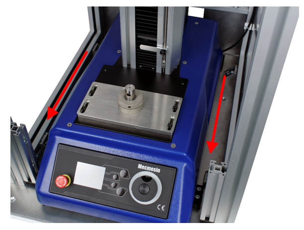
Mecmesin recommends that the test stand and guard assembly are placed so that the front panel is clearly visible and can be reached. For single column test stands, this will typically require the base of the machine to be approximately at waist height.
An example of the recommended operation position is shown in the image above. Here the operator has easy access to the front panel as well as a clear view over the entire test stand.
6 System Diagrams
6.1 MultiTest - 0.5 kN, 1 kN & 2.5 kN
Below is a list of Mecmesin Interlocked Guards compatible with single column MultiTest systems (please note that only 432-682 is shown in the system diagrams):
- 432-680 - MultiTest 0.5 kN Interlocked Guard
- 432-681 - MultiTest 1 kN Interlocked Guard
- 432-682 - MultiTest 2.5 kN Interlocked Guard

| 1 | Door Handle |
|---|---|
| 2 | Clear Polycarbonate Sheet |
| 3 | Control Panel Access |
| 4 | Interlock Mechanism |
| 5 | Rear Panel Access |
6.2 OmniTest - 5 kN & 7.5 kN
Below is a list of Mecmesin Interlocked Guards compatible with single column OmniTest systems:
- 432-684 - OmniTest 5 kN & 7.5 kN Interlocked Guard

| 1 | Door Handle |
|---|---|
| 2 | Clear Polycarbonate Sheet |
| 3 | Control Panel Access |
| 4 | Interlock Mechanism |
| 5 | Rear Panel Access |
6.3 Twin Column Test Stands – 10 kN & 25 kN
Below is a list of all available 10 kN and 25 kN Mecmesin twin column test systems fitted with interlocked guards (please note that 820-010+G/820-025+G is shown in the system diagrams):
- 805-017+G - MultiTest-i 10 kN & Interlocked Guard
- 805-016+G - MultiTest-i 25 kN & Interlocked Guard
- 815-004+G - MultiTest-xt 10 kN & Interlocked Guard
- 815-005+G - MultiTest-xt 25 kN & Interlocked Guard
- 820-010+G - OmniTest 10 kN & Interlocked Guard
- 820-025+G - OmniTest 25 kN & Interlocked Guard

| 1 | Door Handle |
|---|---|
| 2 | Clear Polycarbonate Sheet |
| 3 | Control Panel Access |
| 4 | Side Connectors Panel |
| 5 | Force/Transducer Socket |
6.4 Twin Column Test Systems – 50 kN
Below is a list of all available 50 kN Mecmesin twin column test systems fitted with interlocked guards (please note that only 820-050+G is shown in the system diagrams):
- 805-023+G - MultiTest-i 50 kN & Interlocked Guard
- 815-006+G - MultiTest-xt 50 kN & Interlocked Guard
- 820-050+G - OmniTest 50 kN & Interlocked Guard

| 1 | Door Handle |
|---|---|
| 2 | Clear Polycarbonate Sheet |
| 3 | Control Panel Access |
| 4 | Connectors Panel |
| 5 | Force/Transducer Socket |
7 Unpacking and Parts Supplied
7.1 Single Column Test Stands - Inspection and Unpacking
Information relating such the exact weight and dimensions of each interlocked guard model is located in the 'Specification' section of this manual.
Before installing or operating your Mecmesin guarding please ensure that no visible damage has occurred during the shipping of the guarding.
Important! If any damage is discovered, do not proceed with the installation.
If any damage is present, contact your local supplier immediately who will decide the most appropriate action and rectify the situation as quickly as possible.
7.2 Twin Column Test Stands – Inspection and Unpacking
Mecmesin twin column test stands ordered with interlocked guarding come pre-assembled as one unit. For weight and dimensions of twin column test systems with an additional interlocked guard, please see the 'Specification' section of this manual.
For safe handling and placement of the test stand, please refer to your systems user manual for more information.
7.3 Packaging
We strongly recommend that you retain the packaging for the machine guard as this can be re-used if the device needs to be returned to your authorised Mecmesin distributor for periodic servicing or modification.
7.4 Safe Handling of Single Column Interlock Guards
To install the test stand’s guarding it is required to lift and move the interlocked guard, improper lifting technique or handling of the guard could lead to injury or damage to the equipment.
Before moving the guard, an assessment should be carried out by a qualified individual to determine how to move the guarding safely.
7.5 Additional Items Supplied with Your Guard
The items supplied with your guard varies depending on the model. The next section contains a list of the parts supplied with the interlocked guard. Please note some items are only supplied for xt systems.
7.5.1 432-680, 432-681, 432-682 - MultiTest 0.5 kN, 1 kN, 2.5 kN
| Part No. | Description | Qty |
|---|---|---|
| 409-080 | Guard Foot Spacer Block | 4 |
| 420-638 | M6 x 35 Skt Cap | 4 |
| - | Guard Door Key | 2 |
| 408-843 | 10mm Tee Slot Nut (only required for xt-console mounting) | 1 |
| 408-921 | Console Arm Mounting Bracket (only required for xt-console mounting) | 1 |
| 420-076 | M5x5 Grub Screw (only required for xt-console mounting) | 2 |
| 420-536 | M8x12 Skt Cap (only required for xt-console mounting) | 2 |
7.5.2 432-684 - OmniTest 5 kN & 7.5 kN Only
| Part No. | Description | Qty |
|---|---|---|
| - | Guard Door Key | 2 |
7.5.3 10 kN, 25 kN and 50 kN Twin Column Guarded Systems
| Part No. | Description | Qty |
|---|---|---|
| - | Guard Door Key | 2 |
| 408-921 | Console Arm Mounting Bracket (Only required for xt-console mounting) | 4 |
| 420-536 | M8 x 12 mm Socket Cap (Only required for xt-console mounting) | 2 |
8 Single Column Guard Installation
Before installing a single column guard, it is important to read the next section in full, failure to do so could lead to injury or damage to the test equipment.
8.1 Prerequisites
Before installing your single column guarding, ensure you are working in a suitable area.
It is important that there is a clear, stable work surface to place both the guard and the associated test stand that is suitable to secure the system to, and that all potential risks have been assessed before starting the installation phase.
Installation of interlocked machine guarding should only be carried out by qualified, authorised personnel.
Failure to follow the installation instructions within this manual could result in serious injury to the user or those around the machinery. It could also cause damage to the equipment or surrounding environment.
8.2 MultiTest Single Column - Installation Guide

Locate the four right-angled brackets that connect the guard to the lower base plate. These are circled in the image above.

Using a suitable metric hex key remove the existing fixings from the lower section of the right-angled bracket as shown in the image above. This will release the lower base plate from the guard.

Carefully lift the upper guard away from the base plate and place it to one side on a suitable work surface.

Remove the four rubber feet from their threaded holes located on the bottom of the MultiTest system using a suitable flat head screwdriver. This is shown in the image above.
These holes will be used to mount the guard’s baseplate to the bottom of the test stand.

Secure the guard’s baseplate to the test stand using the four supplied M6 x 35 mm countersunk screws (420-638).
Each screw should pass through the guard’s baseplate, then through one of the supplied spacers (409-080), before locating in the threaded holes on the bottom of the test stand. This is shown in the image below.

These spacers must be fitted between the guard’s baseplate and the test stand to ensure the stand is sufficiently cooled during operation.

For taller test stands (0.5 kN and 1 kN), it may be necessary to lay the stand on its back to fit the cover. Ensure that the stand is supported when placed in this position.
Lower the main guard body over the test stand and secure it to the base plate using the four supplied screws that had been previously removed. This is shown in the image above. An example of the complete assembly is displayed below.


Using suitable fixings secure the test stand and guard assembly to the workbench using the countersunk mounting holes circled in the image above. It is recommended that through bolts are used with retaining nuts on the underside of the work surface; washers should be used between the work surface and the retaining nuts.
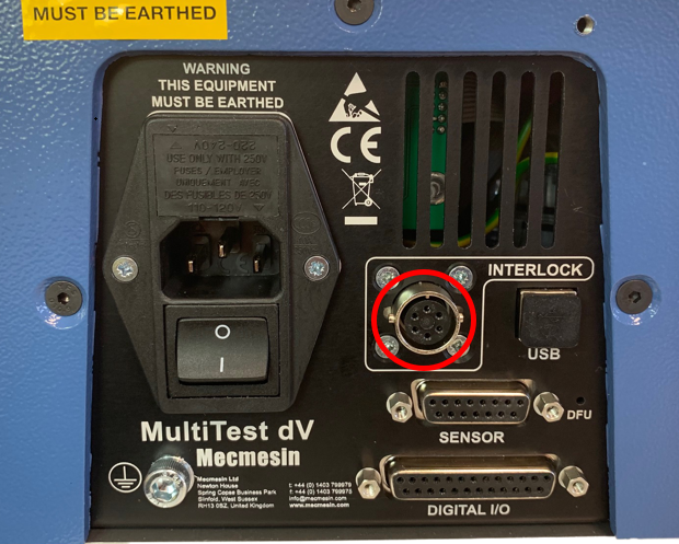 MultiTest-dV Rear Panel
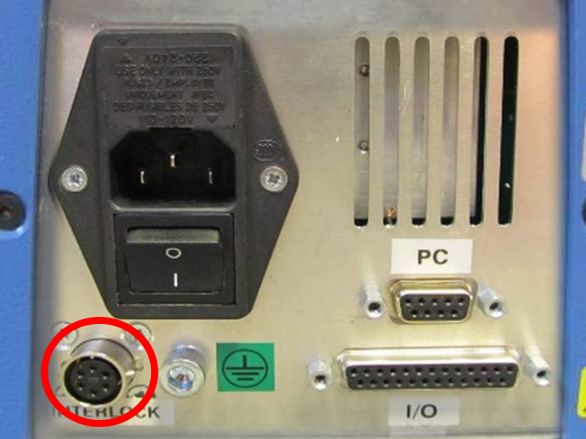 MultiTest-i Single Column Rear Panel
Locate the external interlock guard loom and feed it around to the MultiTest rear connectors panel. Ensuring that the cable is not trapped or close to any moving parts.
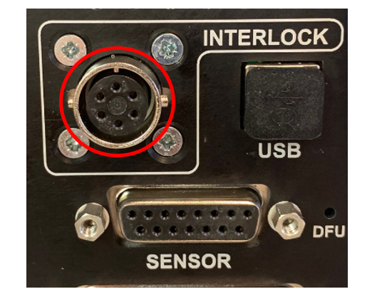
Remove the plastic covering from the end of the cable and connect it to the appropriate MultiTest’s rear panel 6-way socket marked 'INTERLOCK', as shown in the images above.
8.3 OmniTest Single Column – Installation Guide
The guard can be fitted by either lowering it over the test stand or sliding it in from the rear (used if ceiling height prevents the first method).
If the guard is to be lowered on to the test stand continue to Step 3. If the guard is to be slid in from the rear of the test stand proceed to sub-section 'Rear Slide Assemble'.
Locate the four right-angled brackets that connect the guard to the lower base plate, these are circled in the image above.
Using a suitable metric hex key remove the fixings screws from the lower section of the right-angled bracket, as shown in the image above. This will release the lower base plate from the guard.
Carefully lift the upper guard away from the base plate and place it to one side on a suitable work surface.

First, the front foot stops will need to be removed before locating the OmniTest single column stand to the base plate.
Next, carefully slide the OmniTest on to the plate locating the test stand’s rear feet between the two rear foot stops. The rear foot stops are shown in the image above.

Once the OmniTest is located in the rear two stops, fit and secure the front foot stops using the supplied cap head screws. The secured assembly is shown in the image above.

It may be necessary to lay the stand on its back to fit the cover. Ensuring that the stand is supported when placed in this position.
Lower the main guard body over the test stand and secure it the base plate using the four screws that had been previously removed. This is shown in the image above. An example of the complete assembly is displayed below.


To prevent the test stand from toppling it is advised that the test stand and guard assemblies are secured to a level workbench. The holes circled in the image above should be used to secure the assembly. The holes are 6mm in diameter and are countersunk. Dimensions for the holes can be found in the 'Specification' section.

Locate the external interlock guard loom and carefully fit it to the OmniTest’s rear connectors panel. Ensuring that the cable is not trapped or close to any moving parts.
Remove the plastic covering from the end of the cable and connect it to the OmniTest’s rear panel 6-way socket marked 'INTERLOCK', as shown in the image to the right.
8.3.1 Rear Slide Assembly Method
The following steps cover how to fit the guarding from the rear of the test stand.
To slide the guard in from the rear of the test stand, as opposed to lowering it from the top of the test stand, the front extrusion will need to be removed.

Remove the top caps from both each side of the lower front extrusion, as shown in the images above. The cap should be moved upward to release it from the extrusion, this is displayed in the image below.


Use an Allen key to loosen the two retaining screws in the front extrusion as shown in the image above.

Once both screws have been loosened, carefully lift the extrusion section upwards to remove.
First, the front foot stops will need to be removed before locating the OmniTest single column stand to the base plate.
Next, carefully slide the OmniTest on to the plate locating the test stand’s rear feet between the two rear foot stops. The rear foot stops are shown in the image above.
Once the OmniTest is located in the rear two stops, fit and secure the front foot stops using the supplied cap head screws. The secured assembly is shown in the image above.
Pictured above is the guard, with the front frame section and door removed, ready to be fitted to the test stand.
 The guard can now be slid into place from the rear of the test stand, taking care not to cause damage during this process.
 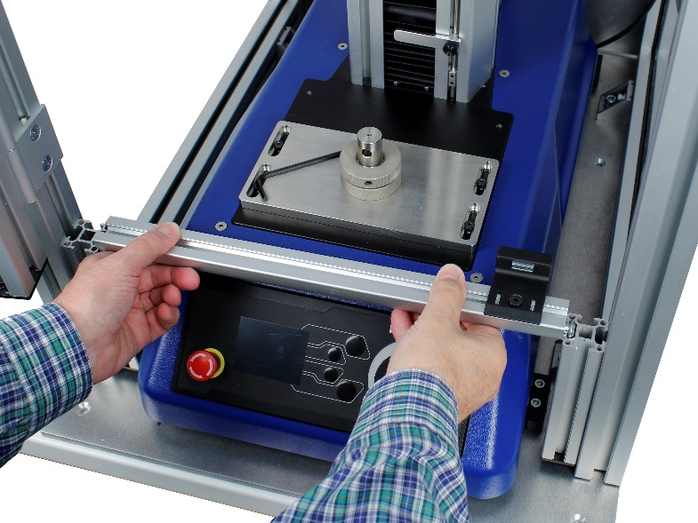 The next step is to re-attach the front extrusion. First, position the extrusion as shown in the image above
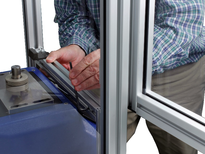 Then tighten the fixings as shown
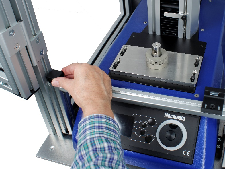 Once the extrusion is secured, re-fit the top caps to each section.
Locate the external interlock guard loom and carefully fit to the OmniTest’s rear connectors panel. Ensuring that the cable is not trapped or close to any moving parts.
Remove the plastic covering from the end of the cable and connect it to the OmniTest’s rear panel 6-way socket marked 'INTERLOCK', as shown in the image to the right.
8.4 xt Console Installation
For xt systems, the console needs to be fitted to the guarding, instead of the test stand. This can be completed by following the steps below. Please note Steps 1 and 2 only apply to single column test stands; twin column test stands come with the Tee-slot nut fitted.

To prevent the console from being obscured by the guarding’s door, it is recommended that the xt console is fitted to the right-front extrusion, (this is highlighted in the image above). Remove the top cap from the right-hand extrusion, as shown in the image below.


Slide the supplied 10mm Tee-slot nut (part number 408-843) into the extrusion. Ensure that the Tee-slot nut is oriented, so the two M8 holes are at the top.

Position the nut as per the image above; this should be just above the door latch. Lock the Tee-slot nut it in place using the two supplied grub screws provided into the holes highlighted above.

With the Tee-slot nut in position, align the holes in the console arm mounting bracket with the M8 holes in the Tee-slot nut.

The image above shows the mounting bracket secured to the guarding’s extrusion. When fitting, ensure the bracket is correctly aligned to the frame before securing it in place with the two supplied cap screws.

Fit the console arm to the rear of the mounting bracket using the two supplied countersunk Torx-head screws.

The image above shows the console arm and xt console correctly fitted to the guarding.

If the height of the console arm needs adjusting, unscrew both supplied socket cap screws and remove the mounting bracket with the console.

Slacken off the M5 grub screws using an Allen key and slide the bracket to the desired height. Tighten the grub screws and then refit the mounting bracket and console.
8.4.1 Single Column Override Plug

Single column test stands below 5 kN use an override plug, instead of a key switch, to override the interlock circuit. The override plug is shown in the image above.
To override the guard and allow the use of the test stand without the guard’s interlock function active, fit the override plug to the interlock socket located on the test stand’s rear connectors panel, as highlighted in the image above.
To activate the interlock guard, remove the override plug, ensuring it is stored in a safe location, and connect the guard’s loom to the interlock socket located on test stand’s rear connectors panel.
8.5 Twin Column Guard Bung
To allow addition cables to pass through the guarding there is an additional hole located next to ELS socket, as shown in the image below:

You can remove the twin column guard bung by pushing it out from inside of the guard.

8.6 Checking the Interlock Function and Operation
Once the installation is complete, the next step is to test the interlock circuit. First, ensure that all required cables have been connected to the machine and the device is switched on and ready to use. The interlock’s functionality is described below.
A set of interlock keys are provided, these are used to enable and disable the interlock circuit.
For single column test stands below 5 kN, an interlock override plug is provided with the test stand. This is fitted to the stands rear panel connector to disable the test stand’s interlock circuit instead of using a key switch.
8.6.1 Interlock Key Switch Set to ‘0’ (Override Plug Connected)

With the key switch set to the ‘0’ position (key horizontal), the interlock circuit is disabled and the guard door can be opened without error.
The test stand can be moved up or down freely and cannot be interrupted by the interlocked guard.
For single column test stands below 5 kN, the interlock override plug should be fitted in place of the guard’s connector. This will allow the system to be moved freely without interruption from the interlock circuit.
8.6.2 Interlock Key Switch Set to ‘1’ (Interlocked Guard Connected)

With the interlock cable fitted and the key switch set to the ‘1’ position (key vertical), the interlock circuit function is enabled.
For single column test stands below 5 kN, simply fit the interlocked guard’s connector in place of the override plug.
Opening the door will inhibit the motor drive of the test stand, and a warning will be displayed on the front panel (OmniTest and dV test stands only) and software (if connected). The user can not move the machine. If a test is in operation as the door is opened, the test will be immediately stopped.
8.7 MultiTest-dV and OmniTest Interlock Function Test
The following section only applies to MultiTest-dV and OmniTest systems.
Work through the table below row-by-row setting the interlock key switch as per the first column and the guard door position as per the second column.
For MultiTest-dV test stands, fit the interlock override plug when the first column states a switch position of ‘0’ and the interlocked guard’s connector at switch position of ‘1’.
Next, invoke the test stand operation stated in the third column. This will involve either manually jogging the test stand or attempting to run a test. Check the error message and front panel status of the test stand against the ‘Error Message’ and ‘Front Panel’ columns:
| Switch Position | Guard Door Status | Stand Operation | Error Message | Front Panel | VectorPro Message |
| 0 | Door Closed | Jog UP or DOWN | None |  |
None |
| 0 | Open Guard Door | Jog UP or DOWN | None | |
None |
| 0 | Open Guard Door | RUN Test | None | |
None |
| 1 | Door Closed | Jog UP or DOWN | None |  |
None |
| 1 | Open Guard Door | Jog UP or DOWN | INTERLOCK ACTIVE | |
Warning Message Displayed |
| 1 | Open Guard Door | RUN Test | INTERLOCK ACTIVE | |
Warning Message Displayed |
Please refer to the section 'VectorPro - Warning Message' for more information relating to VectorPro warning messages.
8.8 MultiTest-i Interlock Function Test
The following section only applies to MultiTest-i test stands.
Work through the table below row-by-row setting the interlock key switch as per the first column and the guard door position as per the second column.
Next, invoke the stand operation stated in the third column, this will involve either jogging the test stand in Emperor or attempting to run a test. Check any error message in Emperor against the ‘Error Message’ column in the table:
| Switch Position | Guard Door Status | Stand Operation | Software Error Message |
| 0 | Door Closed | Jog UP or DOWN | None |
| 0 | Open Guard Door | Jog UP or DOWN | None |
| 0 | Open Guard Door | RUN Test | None |
| 1 | Door Closed | Jog UP or DOWN | None |
| 1 | Open Guard Door | Jog UP or DOWN | INTERLOCK OPENED |
| 1 | Open Guard Door | RUN Test | INTERLOCK OPENED |
Please refer to the section 'Emperor - Warning Message' for more information relating to Emperor warning messages.
9 Operation
9.1 Scope of Use
Mecmesin interlocked guarding helps to provide additional ingress protection against foreign objects while also reducing the risk of an operator coming into contact with a moving test stand.
The guard is designed to be used in a dry, clean and tidy environment and should be placed on a stable and load appropriate work platform away from potentially hazardous environments or items.
Mecmesin motorised test stands are designed to be used while under constant supervision, the addition of an interlocked guard does not alter this requirement, failure to monitor a test stand in operation could lead to damage to the equipment or injury to others.
The interlocked machine guard has the following primary functions:
- Provide ingress protection to operators when using the machine. To prevent hand trap conditions or deliberate interaction with the test area during the test sequence.
- The ability to end a test sequence or ensure that the machine motor drive is inhibited if the interlock circuit is broken (door opened).
- Permanently enable/disable interlock function with a removable key or override plug.
9.2 MultiTest-dV and OmniTest Interlocked Guard Examples
9.2.1 Example 1
| Switch Position | Guard Door Status | Stand Operation | Error Message | Front Panel | VectorPro Message |
|---|---|---|---|---|---|
| 0 | Door Closed | Jog UP or DOWN | None | |
None |
In this example, the authorised user requires the door to be open while jogging the test stand. A scenario where jogging the machine with the door open may be beneficial is when first fitting a set of grips to the test stand.
As the interlock key switch is set to ‘0’ (override plug connected for MultiTest-dV test stands), the guarding does not restrict the test stand’s movement and the system can be jogged with the door open.
If the interlock key switch is set back to ‘1’ (interlock guard connected for MultiTest-dV test stands) the operator will be unable to jog the machine with the door open.
9.2.2 Example 2
| Switch Position | Guard Door Status | Stand Operation | Error Message | Front Panel | VectorPro Message |
|---|---|---|---|---|---|
| 1 | Open Guard Door | Jog UP or DOWN | INTERLOCK ACTIVE | |
Warning Message Displayed |
In this example, the operator is attempting to jog the test stand with the door open, but the stand will not move.
As the interlock system is active, the test stand is displaying the error message ‘INTERLOCK ACTIVE’. The test stand’s motor will remain restricted until the door is closed. Once the door is closed the error condition will disappear, allowing the test stand to be moved.
9.2.3 Example 3
| Switch Position | Guard Door Status | Stand Operation | Error Message | Front Panel | VectorPro Message |
|---|---|---|---|---|---|
| 1 | Operator Opens Guard Door | Test Running | INTERLOCK ACTIVE | |
Warning Message Displayed |
In this example, the operator has opened the guard door while the test was running. As the interlock system is active, the test will immediately stop, and the test stand will display the following message ‘INTERLOCK ACTIVE’.
If the test stand is being used injunction with VectorPro, the data capture for the sample will be aborted and a warning message will be displayed. The motor drive will remain inhibited until the door is closed.
9.2.4 VectorPro™ - Warning Message
If the interlocked guard door is opened during a test (and the interlock system is active) the warning message shown below will be displayed:

At this point, the test will be aborted, and the machine drive will be inhibited. Closing the guard door will remove the machine display panel error, but the test sample being recorded in VectorPro cannot be continued. The test is automatically aborted.
9.2.5 VectorPro™ - Pause Operation
When using VectorPro in conjunction with an interlocked machine guard, certain operations allow for the guard warnings to be overwritten. These timeline operations are in the ‘Pause’ section of VectorPro and they allow the door to be opened without aborting a test.
When a ‘Pause’ operation in the test timeline is reached, the test stand will stop and the window shown below is displayed onscreen. This indicates which button to press on the front panel to continue the test.

While the test is paused, the guard door may be opened and closed. Once ‘Play’ is pressed, the test will continue. If the door is left open when pressing ‘Play’, the test will immediately abort.
Opening the guard door without a software ‘Pause’ active will also operate the interlock circuit in the usual manner.

During a ‘Pause’ operation, the following message will be displayed on the test stand’s front panel when opening the guard; ‘Interlock Active !’. This is shown in the image above.
For more information relating to ‘Pause’ operations, please read on from the section 'Pause Operations' of the 'VectorPro™ User Manual - Designing a Test MT Version'.
9.2.6 VectorPro™ - Pause Operation Safety
When using a ‘Pause’ function in conjunction with a Mecmesin interlocked guard, the following information should be observed:
9.3 MultiTest-i and xt Interlocked Guard Examples
9.3.1 Example 1
| Switch Position | Guard Door Status | Stand Operation | Software Error Message |
|---|---|---|---|
| 0 | Door Closed | Jog UP or DOWN | None |
In this example, the authorised user requires the door to be open will jogging the test stand. A scenario where jogging the machine with the door open may be beneficial is when first fitting a set of grips to the test stand.
As the interlock key switch is set to ‘0’ (override plug fitted for single column systems) the guarding does not restrict the test stand’s movement. The system can be jogged with the door open.
If the interlock key switch is set back to ‘1’ (override plug removed for single column test stand and the guard loom connected) the operator will be unable to jog the machine with the door open.
9.3.2 Example 2
| Switch Position | Guard Door Status | Stand Operation | Software Error Message |
|---|---|---|---|
| 1 | Open Guard Door | Jog UP or DOWN | INTERLOCK OPENED |
In this example, the operator is attempting to jog the test stand with the door open, but the stand will not move as the interlock system is active.
Emperor will display a pop-up window with the following message ‘Emergency stop button pressed or interlock opened…’.
The test stand’s motor will remain restricted until the error condition is removed. To re-enable the test stand’s motor drive, close the door and press ‘OK’ on the pop-up window displayed in Emperor. See the section 'Emperor - Warning Message' for more information.
9.3.3 Example 3
| Switch Position | Guard Door Status | Stand Operation | Software Error Message |
|---|---|---|---|
| 1 | Operator Opens Guard Door | Test Running | INTERLOCK OPENED |
In this example, the operator has opened the guard door while the test was running. As the interlock system is active, the test will immediately stop, and the Emperor will display a pop-up window with the following message ‘Emergency stop button pressed or interlock opened…’.
The test stand’s motor will remain restricted until the error condition is removed.
To re-enable the test stand’s motor drive, close the door and press ‘OK’ on the pop-up window displayed in Emperor. See the section 'Emperor - Warning Message' for more information.
9.3.4 Emperor - Warning Message
If the interlocked guard door is opened (and the interlock system is active) the warning message shown below will be displayed:

At this point, the test stand’s motor drive will be inhibited. If a test is in operation, it will be aborted. To re-enable the test stand’s motor drive, close the door and press ‘OK’ on the pop-up window displayed in Emperor.
Pressing ‘Abort’ will disconnect the test stand and the message shown below will be displayed:

9.4 Responsible Use of Interlock Override
Overriding the guard interlock enables the door to be opened without interrupting the test stand’s ability to move. Although the interlock should, typically, always be functioning (not overridden) there are some scenarios where the interlock may need to be disabled, examples include:
- Test Setup – When first setting up the test stand with grips and sample, it is often necessary to make several manual adjustments to the fixtures. In this scenario overriding the interlock enables better access and visibility of the fixtures, thus helping to reduce setup time when compared to the same procedure with the guard’s interlock active. The interlock should be reactivated upon completing the setup.
- Test Stand Servicing – Certain service procedures will require the interlock to be overridden. Servicing is only to be undertaken by Mecmesin or an approved distributor.
A full risk assessment should be carried out for the process of operating the test stand with the interlocked guard overridden. Clear procedures should be defined to determine when it is safe to operate under these conditions.
10 Servicing, Maintenance and Repair
Once the guard is installed, it should provide a trusted long-term resource for safe and reliable testing.
10.1 Servicing
Mecmesin guards contain no user-serviceable parts and are designed to be service free.
Periodic inspection and maintenance such as cleaning and lubrication of hinges with a machine grade oil are recommended.
10.2 Maintenance & Cleaning
It is advised that periodic inspection of the outside of your guard is performed and your guard is cleaned to enable clear viewing of the test stand and to prevent the build-up of debris or dust.
To clean the guard first remove any loose debris with a soft brush, then wipe down the surfaces of the guarding using a damp cloth. A dry cloth may be used to dry surfaces and remove any watermarks.
10.3 Repair
If the guard fails or appears to behave unusually, contact your local supplier for support. Do not continue to use the test stand until the guarding has been inspected and, if necessary, repaired by Mecmesin or a Mecmesin authorised distributor.
Do not attempt any repairs without consulting Mecmesin or an authorised distributor, doing so may lead to injury, damage of equipment and loss of warranty.
11 Specifications
11.1 Single Column Test Systems
| Machine Guarding | 0.5 | 1 | 2.5 | 5 |
|---|---|---|---|---|
| Guard Part Number | 432-680 | 432-681 | 432-682 | 432-684 |
| Compatible Mecmesin Test Systems | MultiTest-i 0.5 kN | MultiTest-i 1 kN | MultiTest-i 2.5 kN | OmniTest 5 kN |
| MultiTest-xt 0.5 kN | MultiTest-xt 1 kN | MultiTest-xt 2.5 kN | OmniTest 7.5 kN | |
| MultiTest-dV 0.5 kN | MultiTest-dV 1 kN | MultiTest-dV 2.5 kN | ||
| Dimensions | ||||
| Height+ | 1713 mm | 1502 mm | 993 mm | 1163 mm |
| Width | 470 mm | 470 mm | 470 mm | 500 mm |
| Depth (door closed) | 480 mm | 480 mm | 480 mm | 652 mm |
| Max Depth (door open) | 803 mm | 803 mm | 803 mm | 1015 mm |
| Weight (guard only) | 42 kg | 39 kg | 30 kg | 40 kg |
| Sample/Accessory Space | ||||
| Max Width | 386 mm | 386 mm | 387 mm | 420mm |
| Max Diameter++ | 131 mm | 131 mm | 131 mm | 180 mm (OmniTest 5.0 kN) |
| 134 mm (OmniTest 7.5 kN) | ||||
| Interlocking Device | ||||
| Class | Tongue-actuated position switch | |||
| Installation of Guarding | ||||
| Approved Operator(s) | End-user or Mecmesin representative | |||
| Environment Specification | ||||
| Operating temperature | 10 ◦C to 40 ◦C | |||
| Operating relative humidity | 30 % - 80 % (non-condensing) | |||
+ Excluding guard feet
++ Measured from the centre of the load cell
11.2 Twin Column Test Systems
| Machine Guarding | 10 | 25 | 50 |
|---|---|---|---|
| Compatible Mecmesin Test Systems - guards supplied fitted to test stand. Part number of complete test system shown in brackets | 805-017+G MultiTest-i 10kN + Guard | 805-016+G MultiTest-i 25 kN+ Guard | 805-023+G MultiTest-i 50 kN+ Guard |
| 815-004+G MultiTest-xt 10 kN + Guard | 815-005+G MultiTest-xt 25 kN Guard | 815-006+G MultiTest-xt 50 kN + Guard | |
| 820-010+G OmniTest 10 kN + Guard | 820-025+G OmniTest 25 kN + Guard | 820-059+G OmniTest 50 kN + Guard | |
| Dimensions | |||
| Height+ | 1500 mm | 1500 mm | 1931 mm |
| Width (excl key) | 826 mm | 826 mm | 864 mm |
| Depth (door closed) | 556 mm | 556 mm | 613 mm |
| Max Depth (door open) | 1150 mm | 1150 mm | 1215 mm |
| Weight (system)* | 192 kg | 192 kg | 354 kg |
| Sample/Accessory Space | |||
| Max Width | 366 mm | 366 mm | 420 mm |
| Max Diameter++ | 330 mm | 330 mm | 322 mm |
| Interlocking Device | |||
| Class | Tongue-actuated position switch | ||
| Environment Specification | |||
| Operating temperature | 10 ◦C to 40 ◦C | ||
| Operating relative humidity | 30 % - 80 % (non-condensing) | ||
* Excluding accessories such as attached consoles
++ Measured from the centre of the load cell
12 Dimensions
12.1 MultiTest Single Column


12.2 OmniTest Single Column


12.3 Twin Column Test Systems


13 Certification
To view the 'Declaration of Conformity' for the relevant product type or variant, click on the document number in the table below:
| Product or Variant | Document Number |
|---|---|
| MultiTest-i, xt and FPT (all single column variants) | 431-DoC22 |
| MultiTest-i, xt (all twin column variants) | 431-DoC23 |
| MultiTest-dV (including dV(u), OT-0.5 and OT-1) | 431-DoC24 |
| OmniTest-5, 7.5 (single column) | 431-DoC27 |
| OmniTest-10, 25, 50 (twin column) | 431-DoC28 |
| MultiTest Single Column (interlocked guard only) | 431-DoC32 |
| OmniTest Single Column (interlocked guard only) | 431-DoC33 |