1 Mecmesin Long-Travel Extensometer User Manual

 |
431-969-01 October 2019 |
2 Introduction
Mecmesin Long-Travel Extensometers are designed to be used with Mecmesin OmniTest and MultiTest-dV(u) test systems only.
This document describes the safe installation and operation of the MLTE devices, available in lengths 700mm, 1000mm and 1200mm, in conjunction with OmniTest and MultiTest-dV(u) test stands.
For further guidance relating to software operation refer to the user manual below:
 |
VectorPro™ User Manual - Introduction and Initial Setup (431-955-04) |
For more information relating to a test stands operation, please refer to the user manual supplied with the device.
2.1 User Manual Icons
Throughout this manual, the icons shown below are used to identify important health and safety information as well as additional installation/operation guidance. Do not proceed until each individual message is read and thoroughly understood.
2.1.1 Warning
2.1.2 Caution
2.1.3 Information
3 System Diagrams
3.1 Main System Diagram

| 1 | Top Cap |
|---|---|
| 2 | Bearing Guide Rail |
| 3 | Extensometer Arms (Comprised of an adjustable scissor knife edge and bearing guide) |
| 4 | D-Sub Connector (cable and connector to attach to Mecmesin test stand) |
| 5 | Base Plate |
3.2 Lower System Diagram

| 1 | Extensometer Pulley Cord |
|---|---|
| 2 | Guide Bearing |
| 3 | Guage Length Setting Pin |
| 4 | Guage Length Setting Plate |
| 5 | Lower Bearing Retention Cup |
3.3 Extensometer Arm System Diagram

| 1 | Adjustable Knife Edges |
|---|---|
| 2 | Knife Edge Retaining Screw |
| 3 | Arm Pivot Mechanism |
| 4 | Guage Length Setting Plate |
| 5 | Arm/Scissor Grip |
| 6 | Spring Retention Bolt |
| 7 | Arm Compression Spring |
| 8 | Spring Force Adjustment Thumbwheel |
| 9 | Captive Nut |
3.4 Mounting Holes

| Red Holes | Type C QC Holes - For mounting to MultiTest-dV(u) and OmniTest test stands up to 25kN |
|---|---|
| Blue Holes | Type L QC Holes - For mounting to OmniTest-50 test stands |
4 Unpacking and Parts Supplied
4.1 Inspection and Unpacking
Before installing or operating the MLTE ensure that no visible damage has occurred during the shipping of the device.
4.2 Packaging

We strongly recommend that all packaging is retained for the MLTE as this can be re-used if the device needs to stored or shipped between sites.
4.3 Items Supplied
 Please see the table below for the list of the parts supplied with the MLTE.
| Item | Quantity |
|---|---|
| MLTE | 1 |
| Transit Bracket (Shown above and fitted to MLTE on delivery) | 1 |
| Transit Shoulder Bolt (Shown above and fitted to MLTE on delivery) | 1 |
| Low Compression Spring (Shown above and fitted to MLTE on delivery) | 2 |
| Medium Compression Spring (Shown above) | 2 |
| High Compression Spring (Shown above) | 2 |
| M6 x 20mm Socket Cap Screws (Shown above) | 4 |
| User Manual - Web Address Card (Shown above) | 1 |
| Guage Length Setting Pin (Shown above) | 1 |
4.4 Transit Mechanisms
To ensure that the MLTE is not damaged during shipping three 'Transit' mechanisms are used to prevent the following:
- Movement of the extensometer arms - (bearing cup)
- Individual movement of arms causing pulley cords to detach from the pulleys (transit bolt and bracket)
- Internal counterweight and pulley cord movement that could lead to damage during transportation - (Counterweight mechanism)
The instructions for use or removal of the transit mechanisms are detailed in the sections below.
4.4.1 Counterweight Transit Mechanism

Using a Hex key, remove the two caphead screws located in the counterweight transit mechanism (highlighted above). Each screw should be undone in an anticlockwise direction.

To ensure the screws remain with the device they should be screwed into the two threaded inner holes in the counterweight transit mechanism, as shown in the image above. When securing the screws ensure that they do not interfere with the travel of the counterweight.
4.4.2 Extensometer Arms Transit Mechanisms
 Remove the transit shoulder bolt from the transit bracket. This will free the upper arm from the face of the gauge length setting plate. Use a Hex key to remove the two screws from the transit bracket that secures it to the upper arm (shown in the image above). The screws should be rotated anticlockwise to remove them.
 During transit, the lower extensometer arm is secured in a bearing cup at the base of the MLTE (highlighted above). To remove the arm from the cup, first move the upper arm to the top half of its travel. This ensures the upper extensometer arm is not impacted when releasing the lower arm.
4.4.3 Storing and Transporting the MLTE
If storing or transporting the MLTE device ensure that all three transit mechanisms are secured in place. To achieve this, reverse the steps detailed above.
First, secure the lower bearing cup and extensometer arm transit mechanism before securing the counterweight transit mechanism. Once all three transit mechanisms are in place the device can be transported safely.
It is recommended that when not in use, the MLTE is placed in its original packaging. If the original packaging is unavailable store the MLTE so that it cannot easily topple as this may cause damage to the device.
5 Installing the MLTE
5.1 Prerequisites
Before installing the MLTE, ensure you are working in a suitable area. It is important that there is a clear, stable work surface to place the MLTE during installation and that the associated test stand is suitably secured. All potential risks should be assessed before starting the installation phase.
5.1.1 MLTE Mounting
Before fitting the MLTE, identify the holes located in the base of the test stand that will be used to secure the MLTE and QC fitting:
- For single column OmniTest systems, the MLTE can be fitted to either the anvil plate or directly to the test stand base plate.
- For MultiTest-dV(u) test stands the MLTE secures to the anvil plate only.
- For twin column test stands the MLTE secures directly to the test stand base plate only.
See the following section 'Mounting Holes', for information relating to the MLTE base plate holes.
5.1.1.1 Mounting to an Anvil Plate
For single column test stands using adjustable anvil plates the alignment of the test setup must be checked prior to fitting the MLTE.
Once the MLTE is in place, the anvil plate adjustment screws cannot be altered without removing the device.
To check the alignment of the test setup first loosely fit only the QC fitting to the anvil plate, as shown in the image below.

Using the QC fittings secured to the anvil plate and ELS, ensure that the test setup is aligned by lowering the crosshead of the test stand so that the position of both the upper and lower QC fittings can be compared against each other.
Where necessary make adjustments to the anvil plate position to ensure the test setup is correctly aligned.
Once the system is correctly aligned, remove the QC fitting for the anvil plate and continue to the instructions below.
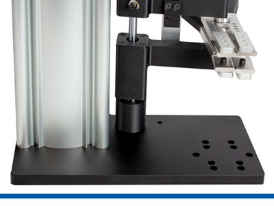
5.2 Fitting the MLTE - Single Column Test Stands
 Once the device is in place secure, the QC Fitting and MLTE base plate to the test stand, or test stand anvil plate, using the 4 x M6 bolts supplied. As shown in the image above (OmniTest-7.5 with no anvil plate is pictured).
5.2.1 Example Test Setup
5.2.1.1 OmniTest Single Column - No Anvil Plate

5.2.1.2 OmniTest Single Column - With Anvil Plate

5.3 Fitting the MLTE - Twin Column Test Stands
With the test stand switched on, use the jog controls to move the crosshead downwards to its lowest possible position. The limit switch activation arm on the right-hand side of the column should be positioned just above it's lowest setting.
Do not move the lower limit hard stop fitting. The adjustable limit switch will need to be loosened and lowered prior to moving the crosshead. See image below for more details:

| 1 | Limit Switch Activation Rod |
| 2 | Adjustable Limit Switch |
| 3 | Lower Limit HardStop |
 With the MLTE on a stable surface, rotate the MLTE so that the longest side of the base plate runs from left to right across the test stand. As shown in the image above (the front of the test stand is represented by the blue line). Ensure safe handling procedures are followed when lifting the device.
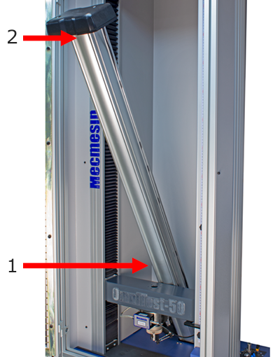 Using safe handling procedures, lift the device and carefully lower the MLTE base into the space behind the twin column crosshead, as indicated by arrow '1' in the image above. The device will need to be angled upon entry behind the crosshead.
Once the lower section of the MLTE is below the crosshead, carefully raise the top of the MLTE into the twin column and stabilise the device as it sits on the test stand base plate, ready for QC fitting. As indicated by arrow '2' in the image above.
Ensure that the MLTE arms and cable do not impact on the twin column crosshead during the fitting process as it may damage the device
 Rotate the MLTE and base through 90°, so that the extensometer arms face towards the front of the test stand, as shown in the image above. Align the holes in the base plate and connect either a QC Type C (For OmniTest 10 & 25 test stands) or Type L (For OmniTest 50 test stands) fitting.
Secure the screws through the QC adaptor to the base plate and tighten with an appropriate 'Hex Key'.
5.3.1 Example Test Setup
5.3.1.1 OmniTest-10/25 - Type C QC

5.3.1.2 OmniTest-50 - Type L QC

5.4 Fitting Grips to the MLTE
 Before attaching the grips to the MLTE ensure the QC adjustment ring is fitted to the QC post, as shown in the image above.
 Once the QC adjustment ring is in place, fit the grip on top of the post and secure the retaining pin. As shown in the image above.
5.5 Extensometer Communication

MLTE devices connect to Mecmesin test stands using a 15-way D-Sub connector:
- For single column OmniTest and MultiTest-dV(u) systems, ensure that the system is powered off, then plug the D-Sub connector into the test stand 'Extensometer' port located on the rear connectors panel. As shown in the image above (OmniTest-5.0 pictured).
- For twin column OmniTest systems, the D-Sub cable is routed through the test stand guarding. Ensure the test stand is switched off and plug the D-Sub into the 'Extensometer' connection on the user access panel, located at the rear right-hand side of the test stand.
Once the D-Sub is in place, secure the connector by tightening the two threaded posts. The posts should only be 'finger' tight, excessive tightening may damage the connector posts.
5.6 Securing the Test Stand
To prevent the test stand from toppling it is strongly advised that single column test stands used in conjunction with MLTE devices are secured to a level workbench.
6 MLTE Operation
MLTE devices are designed to provide accurate displacement measurement through direct contact with the test specimen.
The device can be configured to suit the needs of a wide range of applications, with variable specimen lengths and grip depths.
This next section describes how to configure and operate the MLTE device.
6.1 Extensometer Arm Movement

The extensometer arms allow movement both axially around the bearing guide rail and at the arm pivot mechanism. As shown by the red arrows in the image above.
This range of movement enables the arms to fit samples of varying depths and positions in relation to the test stand, without having to make any adjustment to the test setup. This is illustrated by the green arrows above.
 To open the knife edges on the extensometer compress the black arm sections (as highlighted by the right-hand red arrows in the image above).
This will open the knife edges, enabling the MLTE to be fitted to the test specimen.
6.2 Extensometer Knife Edge Adjustment
The compressive force of the extensometer arm on the test specimen and knife edge profile can be adjusted to best suit the specimen being tested.
6.2.1 Extensometer Arm Compression Strength
 When using the MLTE the compressive grip of the knife edge should be enough so that the specimen does not slip during the test, but without causing damage or stress to the specimen by 'over gripping'.
The compressive (gripping) force exhibiting by the extensometer knife edges on the test specimen can be altered by changing the springs fitted to the extensometer arms.
Each MLTE device is supplied with three sets of springs (shown in the image above):
- High Compression Springs - The highest compression springs supplied. These are typically used with hard to grip specimens where maximum retention force is required. These are the left-hand springs in the image above.
- Medium Compression Springs - Provide a mid-range rated compression spring, ideal for most test specimens. These are the centre springs in the image above.
- Low Compression Springs - Exhibits the lowest gripping force. These springs are ideal for delicate or easy to grip specimens. (Fitted to the MLTE as standard). These are the right-hand springs in the image above.
To change spring sets follow the instructions below. For minor adjustments to the gripping force the spring force adjustment thumbwheel can be used.

The thumbwheel location is shown in the image above. Turning the thumbwheel clockwise increased the gripping force while an anticlockwise movement reduces the force.
 To remove the spring from the extensometer rotate the spring retention bolt in an anticlockwise direction. As highlighted by the red arrow in the image above.
 Once the end of the bolt is removed from the captive nut (located in extensometer arm), unscrew the spring force adjustment thumbwheel from the bolt.
 6.2.2 Range of Movement

The range of movement available to the knife edges can be altered depending on the application requirement.
Using the retaining screw, the knife edge movement can exist in one of two states:
- Rotational Movement Allowed - By tightening the retaining screw until the knife edges are secured, but before the point at which the rotational movement is inhibited, the knife edges have the ability to rotate about the retaining screw, as shown in the illustration above. This enables the knife edges to 'self-align' to the specimen as the extensometer is connected.
- Rotational Movement Inhibited - The retaining screw can be tightened until the point at which the rotational movement of the knife edge is inhibited. This is useful when testing a large batch of geometrically identical specimens, where the 'self-aligning' feature of the knife edge is not required. Fixed knife edges may also be useful if specimen is smaller in cross-section or is prone to cause the non-fixed knife edge to rotate excessively.
6.2.3 Changing Knife Edges
 To provide maximum specimen shape compatibility, the extensometer is supplied with double-sided knife edges that feature two different grip faces:
- 'Chisel Point' knife edge - Provide specimen contact in a sharp profile, allowing precise gripping at a singular point of contact. The left-hand set of knife edges in the image above show the 'Chisel Point' profile as the inner knife edges.
- 'Rounded Face' knifed edge - Provide specimen contact across a 'Rounded' face. Ideal for specimens that easily cut or tear. The right-hand set of knife edges in the image above show the 'Rounded Face' profile as the inner knife edges.
The two faces are located on opposing sides of each jaw. To alternate between the 'Chisel Point' and 'Rounded Face' first remove the knife edge retaining screw.
Once the screw is free, remove the current knife edge and rotate through 180o. Secure it in back in place using the screw.
6.3 Setting the Gauge Length

As standard, the MLTE gauge setting plate offers four set gauge lengths, plus one calibration point: 20 mm, 25 mm, 40 mm and 50 mm.
The gauge length is set using the holes in the gauge length setting plate and the supplied gauge length setting pin, both shown in the image below. By placing the pin in one of the four plate holes and lowering the upper arm onto the pin, the distance between the contact knife edges (gauge length) is set to the distance indicated by the plate.
Below is an example of how to set the gauge length to a specified distance.
 In this example, a gauge length of '40 mm' is required. Insert the gauge length setting pin into the hole identified as '40mm' on the gauge setting plate, as shown in the image above.
6.4 Mounting the Test Specimen
The MLTE is secured to the test specimen using the knife edges located on the extensometer arms.
Following on from the example in the section 'Setting the Gauge Length', below is a step-by-step guide detailing how to fit the MLTE to a test specimen.
 With the gauge length set as per the instructions in the section 'Setting the Gauge Length', and with the upper arm in contact with the gauge length setting pin, open both extensometer arms simultaneously to allow them to be moved into position on the test specimen. Once in place, the extensometer arms should be released allowing the knife edges to close (grip) the test specimen, as shown in the image above.
The image above shows a correctly aligned test setup. The following factors have been correctly implemented:
- The specimen is mounted in parallel to the movement of the test stand's crosshead and there is no unwanted angular displacement in any direction,
- The upper extensometer arm is contacting the gauge length setting pin ensuring the gauge length is set,
- The MLTE has a secure grip on the specimen which is located at the centre of the knife edges.
The MLTE is now ready to test using the test stand and Mecmesin VectorPro software, for more information relating to the operation of VectorPro, see the VectorPro User Manual - Introduction and Initial Setup.
6.5 VectorPro Setup

For more information relating to extensometry operation within VectorPro, please refer to the 'Specimen' section located in the Designing a Test (VectorPro MT Version) User Manual.
For MLTE configuration settings see the section 'Configuring an Extensometer'.
7 Specification
| Long Travel Extensometer | MLTE 700 | MLTE 1000 | MLTE 1200 |
|---|---|---|---|
| Part Number | 432-841 | 432-842 | 432-843 |
| Maximum Usable Range | 510 mm | 780 mm | 980 mm |
| Resolution | 0.010 mm (0.0004”) | ||
| Accuracy | +/- 1% reading over device range, from the first calibration point of 4mm | ||
| ISO 5893 class C & D, ISO 9513 class 1 (from 4mm), ASTM E83 class C (from 4mm) ** | |||
| Minimum Gauge Length | 20 mm (0.787”) | ||
| Maximum Dimension Height | 965 mm (38.00”) | 1245 mm (49.02”) | 1465 mm (57.68”) |
| Width | 265 mm (10.43”) | 265 mm (10.43”) | 265 mm (10.43”) |
| Depth | 185 mm (7.28”) | 185 mm (7.28”) | 185 mm (7.28”) |
| Weight | 6.0 kg | 7.0 kg | 7.7 kg |
| Connector | 15-Way D-Sub | ||
| Mounting | QC Type C or L depending on the test stand | ||
| Suitable Stand to Mount to: | Omnitest 5 * | MultiTest 1-dV * | Omnitest 50 |
| Omnitest 7.5 * | MultiTest 0.5-dV * | ||
| Omnitest 10 | |||
| Omnitest 25 | |||
* Not supplied as standard.
** Calibrated over 0-300mm range with respect to ISO 9513.
8 MLTE Technical Drawing

| MLTE Heights | ||
|---|---|---|
| Part Number | Variant | Height (H1) |
| 432-841 | MLTE 700 | 965 mm |
| 432-842 | MLTE 1000 | 1245 mm |
| 432-843 | MLTE 1200 | 1465 mm |
9 Declaration of Conformity

10 Troubleshooting
If the MLTE arms do not move, or move with a high drag force, the counterweight cord has likely detached from one of the internal pulleys. Situations where this may arise are:
- The device is dropped,
- The device is laid over without the transit mechanisms in place,
- The arms suffer a sudden impact or were moved at excessive speed.
To resolve this issue, firstly remove the top cap from the system using a suitable screwdriver. Once removed the internal pulley arrangement pictured below will be visible.

| 1 | Counterweight and Channel |
|---|---|
| 2 | Rotary Encoder |
| 3 | Upper Arm Pulley |
| 4 | Lower Arm Pulley |
The upper and lower arm pulleys are the first internal elements which the counterweight cord passes through. They are the most likely components to be affected by improper use or mishandling of the device, such as transporting it without the transit mechanisms fitted.
In the image below, the right-hand pulley (upper extensometer arm) shows the correct routing for the cord across the pulley. Note that the cord is free to move and runs in the pulley channel without contacting the cord retention guide.
 In the image above, the left-hand pulley (lower extensometer arm) displays a typical fault that can occur when the device is improperly handled.
Here, the cord has detached from the pulley and is now running across the top plate, which could result in the cord becoming trapped. To resolve the issue, carefully guide the cord back on to the pulley. The design should allow for simple feeding of the cord back around the pulley.
In situations where it is difficult to grip the cord due to its location, it is recommended to use a small instrument such as a Hex Key to lift and guide the cord back onto the pulley.
10.1 Effect on Calibration
Please note at a minimum the system should be checked against known lengths (e.g. verified length bars) after correcting any issues with the pulleys.
If in doubt or if the system is reading incorrectly, contact your local Mecmesin distributor or Mecmesin Technical Support for more information.