 Operating Manual")
- 1 Introduction
- 2 Before Use
- 3 Operation
- 4 Maintenance
- 4.1 Powering the Gauge
- 4.2 Using the Gauge
- 4.2.1 Fitting accessories
- 4.2.2 Mounting to a test stand
- 4.2.3 Powering up
- 4.2.4 Display of Tension/Compression
- 4.2.5 Zeroing the Gauge
- 4.2.6 Changing the unit of measurement
- 4.2.7 Max (Peak) Readings
- 4.2.8 Max Tension
- 4.2.9 Max Compression
- 4.2.10 “Normal” mode
- 4.2.11 Data Output
- 4.2.12 Remote key press from PC
- 4.2.13 Factory Defaults
- 4.3 Optional Settings through Dual Function keys
- 4.4 Dimensions (in Millimetres)
- 4.5 BFG Specification Table
1 Introduction
Thank you for choosing the Mecmesin Basic Force Gauge (BFG) instrument. With correct use and regular re-calibration it will give many years of accurate and reliable service.
The Mecmesin BFG is a member of a series of highly versatile display units. By using the latest integrated circuit technology it has been possible to produce an instrument which can be used to measure tensile and compressive forces accurately, whilst being simple to use by the operator.
2 Before Use
Upon receiving the unit please check that no physical damage has occurred to the packaging material, plastic case or the instrument itself. If any damage is evident please notify Mecmesin immediately.
3 Operation
The most commonly used features such as displaying force, peak hold, zero and changing of displayed units can all be done by pressing a single dedicated key on the front panel.
For less frequently used features a number of “hot keys” are provided, whereby the operator simply presses and holds 2 keys to enable a gauge option.
4 Maintenance
When cleaning the keypad care must be taken to avoid liquids, especially alcohols, seeping around the edge of the membrane. Therefore, we recommend the use of a lightly dampened cloth to avoid liquid spillage onto the membrane.
4.1 Powering the Gauge
The BFG is supplied with a set of 4 Nickel Metal Hydride rechargeable AAA batteries, which are supplied fully charged to allow use straight from the box. Do not use any other battery charger other than that supplied with the force gauge.
4.1.1 Fitting the rechargeable batteries
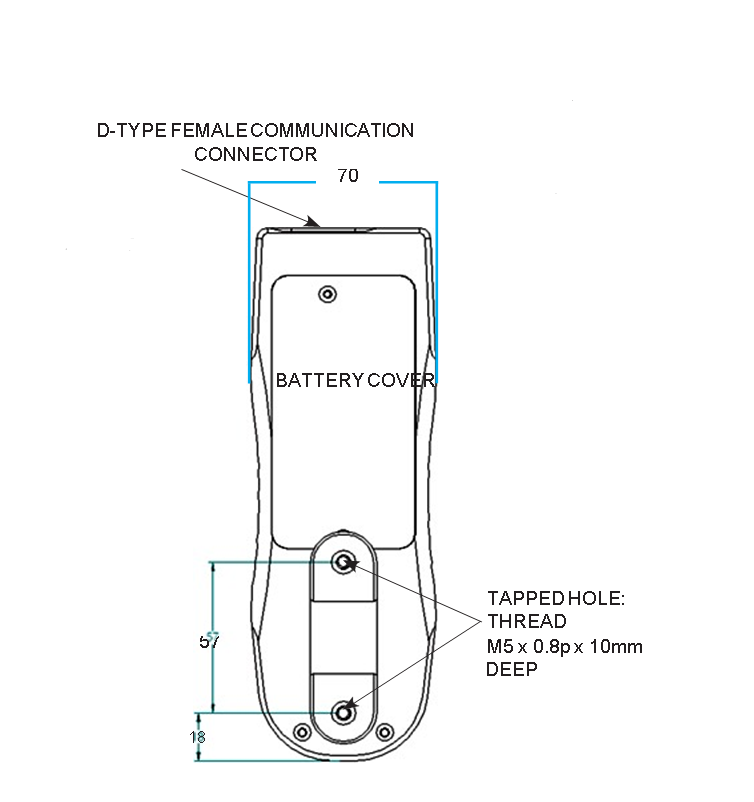
To replace the batteries you must first remove the battery cover on the upper part of the rear of the gauge by removing the 2 retaining screws. Remove the fitted batteries and fit the 4 new batteries in the battery holder ensuring that you observe polarity.
Refit the battery cover and tighten the 2 retaining screws.
4.1.2 Charging the rechargeable batteries
Connect the mains adaptor/charger into the charger socket on the top-right hand-side of the gauge, charge the batteries for 14-16 hours. Only use the adaptor/charger supplied. A fully charged battery pack will provide in excess of 50 hours constant use between charges.
4.1.3 Low battery symbol
If the low battery symbol appears on the display the accuracy of the loadcell reading may be compromised and the gauge will power down after a short period of time.
4.1.4 Mains operation
The BFG can also be powered directly from the mains. This can be achieved with or without the batteries being fitted. Connect the mains adaptor to your mains supply. Only use the adaptor supplied.
4.1.5 Fitting of alkaline batteries
The BFG can also be powered by AAA 1.5V alkaline batteries (not supplied). For fitting of alkaline batteries, follow fitting instructions as per rechargeable batteries above.
Warning: When alkaline batteries are fitted, the mains adaptor/charger must NEVER be connected to the BFG due to risk of acid leakage which could damage the instrument.
4.1.6 Battery safety information
NEVER:
- Short circuit
- Heat or incinerate
- Disassemble or deform cells
- Use alternative chargers other than those supplied by Mecmesin
- Use replacement parts other than those supplied by Mecmesin
- Immerse in water Solder anything to the battery terminals Reverse individual cell polarity
4.2 Using the Gauge
4.2.1 Fitting accessories
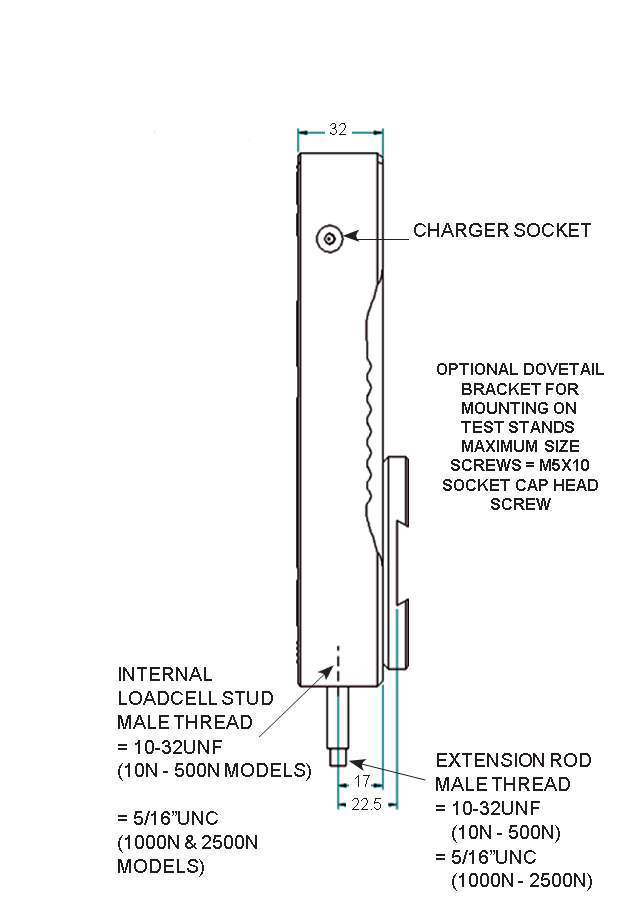
Affix the short extension rod (30mm long) to the loadcell probe in the hole at the bottom of the gauge by tightening it gently with the fingers.
Your chosen grip or accessory may now be connected to the extension rod.
Note: When fitting a grip ensure that it is screwed finger-tight only. Excessive torque or overtightening can
damage the loadcell. Never fit any accessory without first sitting an extension rod.
4.2.2 Mounting to a test stand
On the rear of the gauge there are two M5 threaded holes, which can be used for mounting the gauge to a Mecmesin test stand.
Each Mecmesin test stand is supplied with a dedicated ‘dovetailed mounting bracket’ and screws for this purpose.
If you wish to mount the gauge to another type of stand, ensure that the screws used are threaded into the gauge to a maximum depth of 10mm. If screws are fitted beyond this depth, damage to the loadcell will occur.
4.2.3 Powering up
As shown in Figure 1 the control panel has 5 Function keys plus an On/Off key:
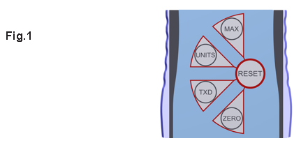

To power up the gauge press the red ![]() key. A short self test runs during which the display will show the model and capacity in newtons.
key. A short self test runs during which the display will show the model and capacity in newtons.
After the self test, providing no load has been applied to the instrument, the display will show all zero’s. This is because the gauge re-zero’s itself during the self test routine.
Please note that a BFG measuring very low forces may not show zero if it is moved during the self test routine. Once it is properly mounted and zeroed the reading will be stable.
If a force is applied perpendicularly via the extension rod to the loadcell, the reading on the display will register the applied force.
Should the instrument have sustained a catastrophic overload, the symbol ‘OL’ will be permanently displayed and the instrument must be returned to Mecmesin or an approved Mecmesin distributor for repair.
Forces greater than 120% of full-scale will produce an OL symbol which will remain on the display all the time the overload is present.
To power down the gauge press the red ![]() key.
key.
4.2.4 Display of Tension/Compression
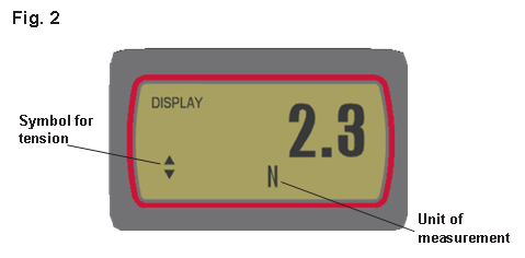
Tensile forces are displayed on the BFG and recognised by the symbol ![]() See Fig 2.
See Fig 2.
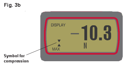
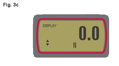
Compressive forces are displayed on the BFG and recognised by the symbol ![]() See Fig 3b.
See Fig 3b.
4.2.5 Zeroing the Gauge
During the operation of the gauge it is often necessary to zero the display - e.g. when you wish to tare out the weight of a grip, so it does not become part of the measured reading. Press and release the ZERO key. The display will blink momentarily as the zero operation is carried out.
4.2.6 Changing the unit of measurement
You can choose from the following units of measurement depending on the capacity of your gauge: millinewtons, kilonewtons, newtons, gram-force, kilogram-force, ounce-force or pound-force.
To change the display units press and release the UNITS key. Each successive key press will select the next available units until the gauge returns to its original setting. The BFG automatically converts readings as new units of measure are selected.
4.2.7 Max (Peak) Readings
The gauge detects and stores maximum (peak) force in both compressive and tensile directions.
4.2.8 Max Tension
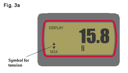
Press the MAX key and the display will show the maximum tensile force identified by the ![]() symbol.
symbol.
4.2.9 Max Compression
Press the MAX key again and the display will show the maximum compressive force identified by the ![]() symbol.
symbol.
4.2.10 “Normal” mode
Press the MAX key again and the display will show the current load applied to the loadcell in either direction, maintaining a “running” display.
Press the RESET key to clear both maximum registers and prepare for detecting the next maximum readings.
4.2.11 Data Output
The BFG has RS232, Mitutoyo and analogue output signals. It is possible to transmit the displayed reading to peripheral devices (e.g. PC, printer) by pressing and releasing the TXD key.
Displayed readings can also be requested individually from a PC via the RS232 interface by sending a “?” (ascii D63 [3fh]) character.
For sending a continuous data stream to a PC, press and hold the TXD key for 2 seconds then release. A ‘1’ will now appear in the display to indicate that data can now be sent. To stop sending data, simply press and release the TXD key, at which point a ‘1’ will disappear from the display.
Please note that the continuous data stream only starts when approximately 2% of the rated capacity of the gauge is reached.
BFG uses 9600 Baud 8 data bits, 1 start bit 1 stop bit and no parity.
When the continuous data stream option is selected the gauge defaults to a BAUD rate of 57,600.
A full range of data cables are available to connect your gauge to peripheral devices – see page 12.
4.2.12 Remote key press from PC
Hold down the Ctrl key on the keyboard and pressing the following keys or sending their equivalent ASCII code as shown in brackets:
a to simulate pressing the TXD key* (ascii DØ1 [Ø1h]) b to simulate pressing the UNITS key (ascii DØ2 [Ø2h]) c to simulate pressing the MAX key (ascii DØ3 [Ø3h])
d to simulate pressing the RESET key (ascii DØ4 [Ø4h])
e to simulate pressing the ZERO key (ascii DØ5 [Ø5h])
Note that the continuous transmission mode cannot be entered via this method
4.2.13 Factory Defaults
The BFG is delivered from the factory with the following settings as default:
Display: “Normal” mode
Auto-off: Not active
Transmit minus sign: Not active
4.3 Optional Settings through Dual Function keys
4.3.1 Auto-off
To conserve battery power, it is possible to activate an Auto-off function so that the gauge powers down after 5 minutes since the last key press or remote request or load change greater than 2% of full scale.
Holding down the ON/OFF key while the gauge ‘boots up’ will either enable or disable the auto-off function (i.e. toggle from its current state). If the auto-off function is enabled then ‘Ao’ is displayed. If the auto-off function is disabled then ‘No Ao’ is displayed. This setting is stored in the memory and is remembered when the gauge is powered down.
4.3.2 Loadcell Diagnostic test
If you suspect that your loadcell transducer has sustained an overload it is possible to check the status of the loadcell immediately.
Symptoms of overload may be (a) OL in display (b) probe not aligned perpendicularly to gauge (c) display will not return to zero (d) F.S.D cannot be achieved (e) instrument readings are not repeatable.
An instrument showing an overload condition cannot be relied upon to provide accurate, repeatable measurement - consult your supplier.
Place the gauge horizontally on a flat level surface without any accessories attached.
Hold down the MAX key whilst turning the gauge on. The value displayed is the percentage difference (Loadcell offset) between the load currently present on the gauge and the gauges first ever calibration relative to full scale counts.
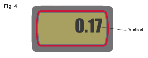
For information: If the % offset is between 5% - 10% it is advisable to contact your supplier to arrange a recalibration of your BFG.
If the % offset is greater than 10% it is advisable to contact your supplier to arrange investigation and repair. These values are given as an indicator only - the need for calibration/repair may vary according to the individual characteristics of the loadcell.
Note: The % offset readings are for indication only and act as guidance and do not give an accurate indication of calibration or loadcell performance
4.3.3 Removing the minus sign during data transmission
Press any key except the ON/OFF key (which will turn the gauge off) to continue using the gauge.
Holding down the TXD key whilst turning the gauge on will enable or disable sending a minus sign with RS232 and Mitutoyo transmission. If the ‘transmit sign’ function is enabled then ‘2’ is displayed in the top row of the display. This setting is stored in the memory and is remembered when the gauge is powered down.
4.3.4 Overload counters
If you suspect that the gauge has been subjected to overloading this can be verified by pressing the UNITS key whilst turning on the gauge this will display the number of overloads in tension first followed by the number in compression. An overload is registered when the load exceeds 120% of the rated capacity.
Removing recorded overloads can only be undertaken by Mecmesin or an approved Mecmesin distributor.
4.3.5 Display messages
| ‘- OL -’ |
Overload - More than 120% of full scale load is currently being applied to the transducer |
| ‘OL’ |
Overload - The peak force reading was applied to the loadcell in excess of 120% of full-scale |
| ‘t-Err’ |
Tare Error - The zero function was performed while the transducer was in an overloaded state |
| ‘No Ao’ |
No Auto off - Automatic power-off is disabled |
| ‘Ao’ |
Auto-off on - Automatic power-off is enabled |
| ‘C-dEF’ |
Calibration default - Invalid calibration data; please notify Mecmesin or an authorised representative for calibration |
| ‘E-dEF’ |
Eeprom error - Memory read error |
| ‘Err 81’ |
Error code 1 - Processor reset error |
If a ‘memory read error’ or ‘processor reset error’ is displayed please contact Mecmesin or an authorised representative to arrange for the BFG to be repaired.
4.4 Dimensions (in Millimetres)
Front View
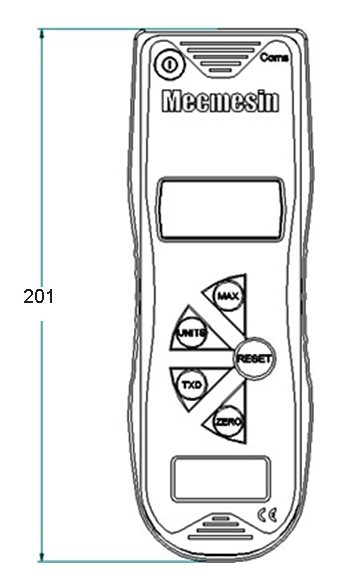
Side View
Rear View
|
|||||||||||||||||||||||||||||||||
Allocation for the pins on the female 15 way ‘D Type’ Communication Connector.
4.5 BFG Specification Table
4.5.1 Range & Resolution
|
Model no: |
mN |
N |
kN |
gf |
kgf |
ozf |
lbf |
|
BFG 10 |
10,000 x 2 |
10 x 0.002 |
- |
1,000 x 0.2 |
1 x 0.0002 |
35 x 0.01 |
2.2 x 0.0005 |
|
BFG 50 |
50,000 x 10 |
50 x 0.01 |
- |
5,000 x 1 |
5 x 0.001 |
180 x 0.05 |
11 x 0.002 |
|
BFG 200 |
- |
200 x 0.05 |
- |
20,000 x 5 |
20 x 0.005 |
720 x 0.2 |
44 x 0.01 |
|
BFG 500 |
- |
500 x 0.1 |
- |
50,000 x 10 |
50 x 0.01 |
1,800 x 0.5 |
110 x 0.02 |
|
BFG 1000 |
- |
1,000 x 0.2 |
1 x 0.0002 |
- |
100 x 0.02 |
3,500 x 1 |
220 x 0.05 |
|
BFG 2500 |
- |
2,500 x 0.5 |
2.5 x 0.0005 |
- |
250 x 0.05 |
9,000 x 2 |
550 x 0.1 |
4.5.2 Accuracy
±0.25% of full-scale
Calibration temperature: 20°C ±2°C Operating temperature: 10°C - 35°C
Temperature shift at zero load: ±0.09% of full-scale/°C
4.5.3 Output
|
RS232-C Digimatic (BCD) Output Analogue |
8 data bits, 1 start bit, 1 stop bit, no parity • +ve output (pin 1) when referenced to ground (pin 10) gives 1.5V output at zero load with typical swing of ±(0.5V to 1V) for full-scale tension/compression • +ve output (pin 1) when referenced to -ve analogue output (pin 9) gives 0V at zero load with typical swing of ±(0.5V to 1V) for full scale tension/compression |