1 System Deflection Compensation (MT Systems Only)
 |
431-955 February 2020 |
2 Introduction
VectorPro™, VectorPro™ MT and VectorPro™ Lite are all registered trademarks of Mecmesin Ltd.
VectorPro is a dedicated software solution used for the programming and acquisition of data from a range of Mecmesin test stands and instruments.
2.1 User Guidance
This user manual section covers System Deflection Compensation (SDC) within VectorPro only, for further guidance relating to other aspects of VectorPro please refer to one of the documents listed below.
2.1.1 VectorPro™ User Manuals
Click one of the links below to navigate to the applicable user manual.
 |
 |
 |
A detailed guide to designing a test for VectorPro MT compliant test systems. |
|
Covers designing a test for VectorPro Lite compliant test stands and devices |
 |
 |
All Tests Viewer and Results Viewer A guide explaining the functionality of the All Tests Viewer and Results Viewer. |
 |
 |
System Deflection Compensation MT Systems Only (Current Document) |
|
View the latest version of the Mecmesin VectorPro Software License Agreement. |
3 SDC - Introduction
Under high loads, a very small element of measured displacement may be due to deflection within the system (test stand, loadcell and fixtures) rather than in the sample under test. The given displacement to create a force may, therefore, be slightly over-indicated.
This system deflection can be measured and compensated for. It can be important where deflection in the sample is similar in magnitude to that in the system, and where very accurate readings are required. SDC is primarily used in top-load testing but can be used in tensile tests (typically where extensometers aren’t being used).
Within VectorPro the test procedure consists of a preload stage, then a run to 90% of the SDC target to exercise the system (not plotted) and then the second run to 95% of the target load (plotted). This final run is saved and is used to determine the deflection compensation. SDC settings are saved in profiles, these can be created, viewed and deleted within the SDC viewer.
4 SDC Viewer
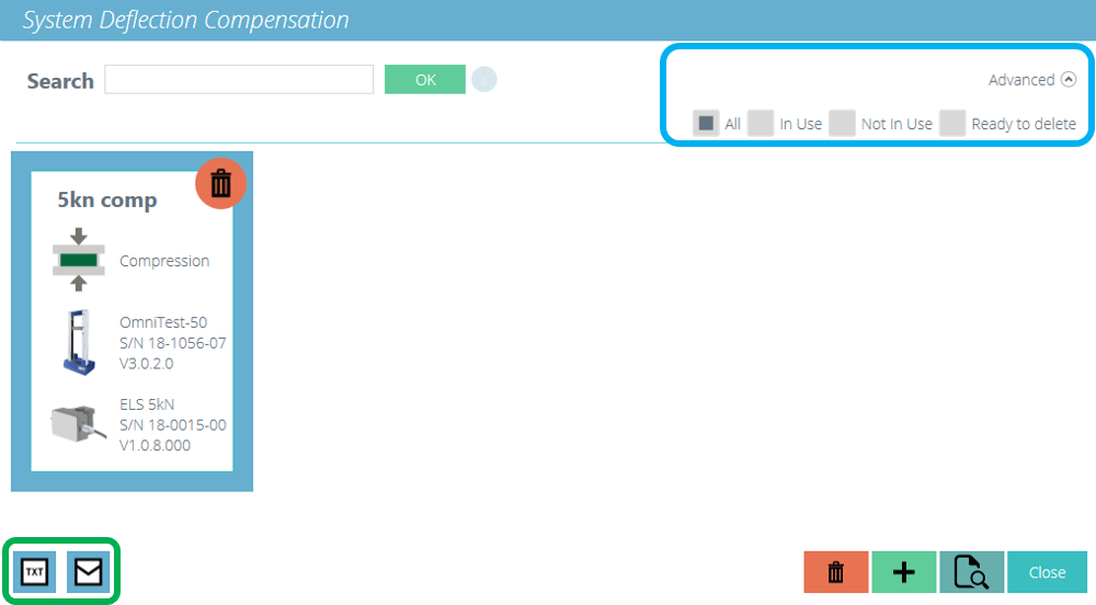
This is accessed by clicking on the SDC tile pictured at the top of this page. This window, allows search for specific SDC profiles and to filter what is currently shown on screen. (Highlighted in blue in the image below).
To export the SDC data as a text file or to send via an email, select the appropriate buttons shown. (Highlighted in green in the image below).
5 Creating a New SDC Profile
| Clicking the ‘Plus’ icon opens the ‘New SDC’ window, simply select the current test stand and then the test mode (compression or tension), to continue. |
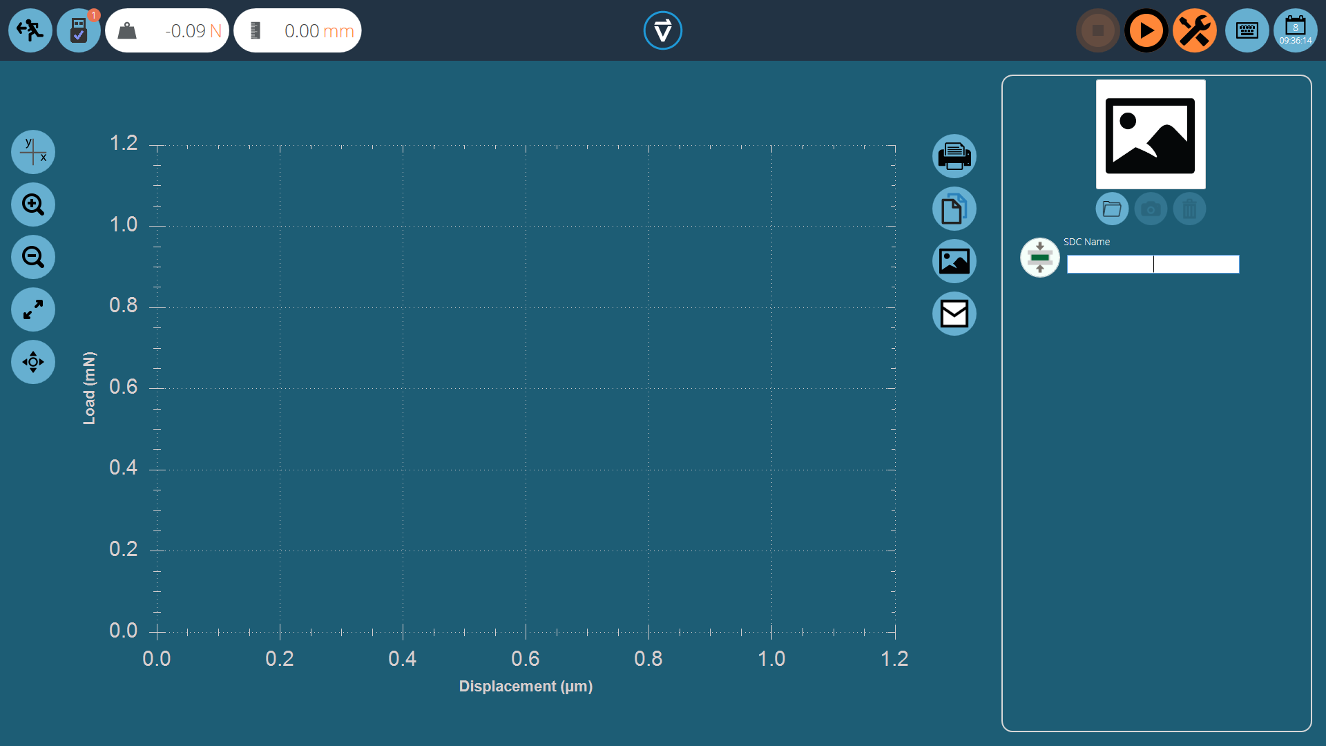
Within the SDC testing screen there are two main sections that are used to monitor and configure the SDC profile:
- Graphic display: This will display a real-time plot of the final SDC run. The graph can be exported as an email file or printed.
- SDC settings panel: The settings panel is located on the right-hand side of the screen, initial options are to name the test and load an image that will serve as the icon for this SDC profile.
5.1 SDC Profile Image
Custom images can be loaded to serve as the icon for the selected SDC profile, this enables easy visual recognition of grips and fixture setups through the icon of the profile. It is recommended that the chosen image clearly shows:
- The load cell used,
- The grip being used,
- Any addition fixtures,
- Test stand (if using multiple test stands).
| To load an image select the folder icon and browse to the desired image using the explorer window. Users with webcams can press the camera icon to take an image. To clear a selected image press the trash icon. |
6 Performing an SDC Test
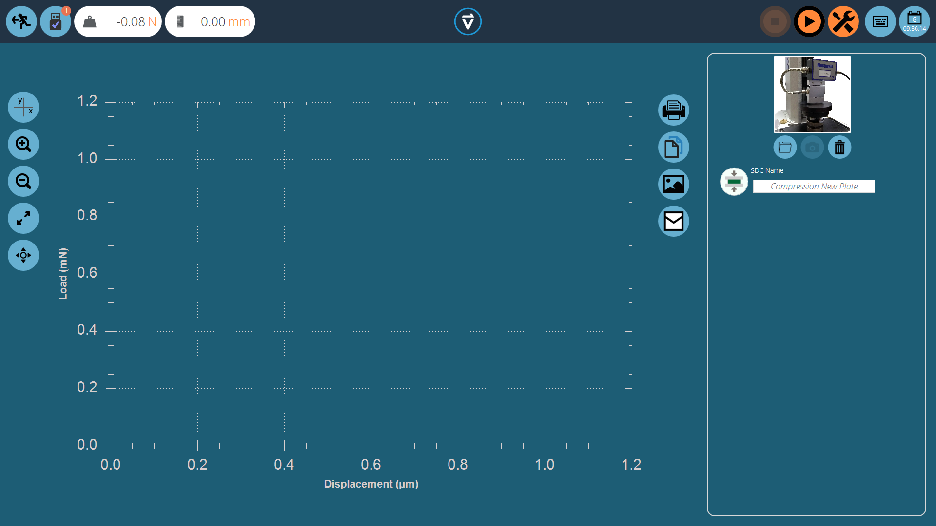
Attach the required stand accessories (grips, plate and probe) without a sample. For force stands requiring compensation corrections in the compression direction, place the compression plate or probe very close to the anvil.
For SDC tests in tension, use a component with a higher tensile strength in place of your specimen. It is important that the specimen exhibits minimal deflection during the SDC test.
Once a suitable image is loaded and named to your SDC profile, ensure the test system is ready to run.
6.1 SDC Test Sequence
First, use the tare command, located in the top-right header bar, to zero the displacement and load values, then press the play command to continue.

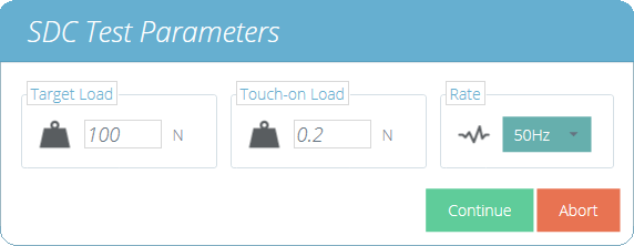
The test parameter window, pictured above, will appear on the screen. Enter a suitable Touch-on Load and the desired target load. The data rate for the test can also be configured using the drop-down box on the right-hand side of the window. Once ready press continue.
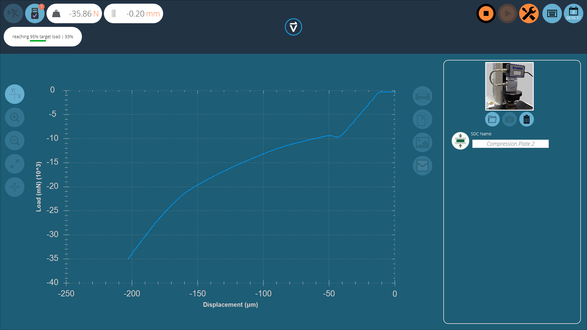
The test will now begin, the initial two stages (pre-load phase and 90% run) are not captured. Test status is indicated by the progress bar located in the upper left corner (pictured above).
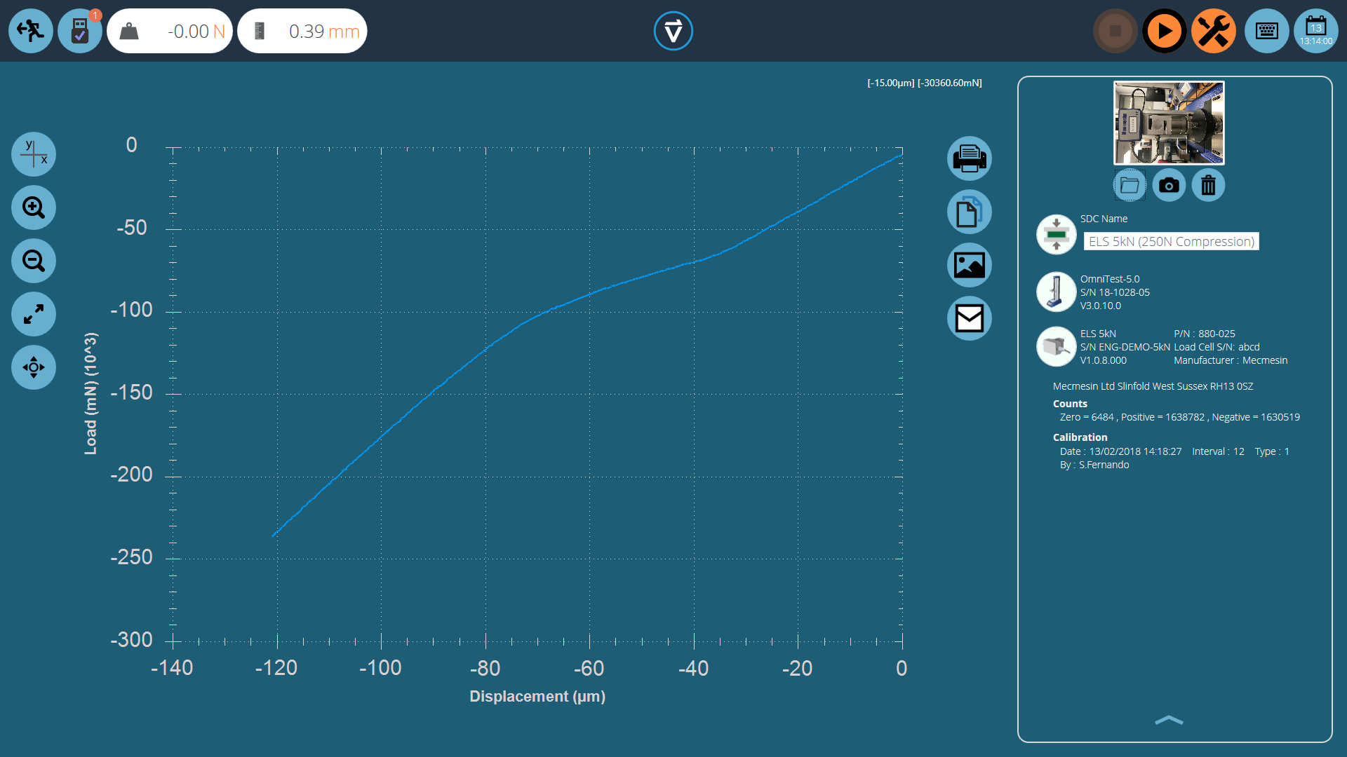
During the final 95% run the data will be captured, the image below shows a curve for an Omnitest-5 being run in compression. Values are captured in mN and µm.
Once the test is completed the graph will be shown in the main display area and the test details are stored in the right-hand plane.
7 SDC Test Information Panel
The right-hand plane stores the test results as well as test stand and ELS information. The diagram below explains what each of the sections represents.
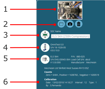
| 1 | SDC profile image |
|---|---|
| 2 | Image controls |
| 3 | SDC direction icon |
| 4 | Test stand information: Stand type, serial number and firmware version |
| 5 | ELS information: Capacity, part number, serial number and firmware version |
| 6 | ELS calibration information. Displays the raw calibration information, date of calibration and who calibrated the device |
8 Saving and Loading SDC Results

To save the SDC results simply press the back button located at the top of the screen and then click the ‘Yes’ button in the ‘Save SDC Test’ window.
SDC profiles are loaded for each individual test rather than as a global profile. SDC profiles can be loaded via the settings menu on the ‘Operations’ tab of the test designer screen.
 |
Simply click the folder icon then load the selected profile. For more information relating to loading an SDC profile, please refer to the 'Test Acquisition Settings' section located in the Introduction and Initial Setup User Manual. |
9 Further Information
For more information relating to VectorPro, please return to the User Guidance section of this user manual and continue to the next applicable user manual.