Operating Manual")
1 Introduction
Thank you for choosing Mecmesin’s Compact Force Gauge+ (CFG+). With correct use and regular re-calibration it will provide many years of accurate and reliable service.
The CFG+ is the elementary member of a series of highly versatile display units. Specifically designed for performing basic tension and compression tests, the CFG+ can be used handheld or fixed to a manual or motorised test stand.
2 Before Use
Upon receiving the unit please check that no physical damage has occurred to the packaging material or the instrument itself. If any damage is evident please notify Mecmesin or your local distributor immediately.
3 Operation
The most commonly used features, such as displaying force, peak hold, zero and changing of displayed units of measurement can all be done by pressing a single dedicated key on the front panel - see page 6, Basic Functions.
3.1 Powering the Gauge
The CFG+ is supplied with a set of 4 x 1.5V AA batteries. To fit the batteries you must first remove the battery cover on the upper part of the rear of the gauge. To release the battery cover press the battery cover as indicated by the arrow and slide the cover upwards. Fit the batteries in the battery holder ensuring that you observe polarity. Incorrect insertion of batteries can cause damage to the gauge.
To replace the battery cover slide it from the top edge of the gauge until it clicks into place.
If the gauge is not going to be used for 3 months or more the batteries should be removed and stored separately. (Settings and calibration data will not be lost if the batteries are removed).
3.1.1 Replacing batteries - Low battery symbol
If the low battery symbol appears on the display the gauge will power-off unconditionally at intervals of one minute. The gauge may be repowered but will power-off every one minute as long as the low battery symbol remains on the display.
This feature has been designed into the gauge to protect the integrity of displayed readings because when the low battery symbol appears the accuracy of the loadcell reading may be compromised.
When the low battery symbol appears on the display, fit four new 1.5V AA batteries in the gauge.
Rechargeable batteries should not be used in the CFG+.
3.1.2 Mains operation
The CFG+ can also be powered directly from the mains using an AC Power Adaptor plugged into the right hand side of the gauge (available as an optional extra). Using an incorrect power adaptor can damage the gauge.
3.1.3 Battery safety information
NEVER:
- Short circuit
- Heat or incinerate
- Disassemble or deform cells
- Immerse in water
- Solder anything to the battery terminals Reverse individual cell polarity
- Use alternative chargers other than that supplied by Mecmesin (Available as an optional extra)
- Use replacement parts other than that supplied by Mecmesin
Never dispose of batteries with ‘normal’ refuse. Contact your local Environmental Authority to determine the location of your appropriate disposal facility.
3.2 Using the Gauge
3.2.1 Fitting accessories
All CFG+ instruments are supplied with a short extension rod (30mm long). This fits directly onto the loadcell mounted in the bottom of the CFG+.
Note: When fitting the extension rod always ensure that it is screwed finger-tight only. Excessive torque or overtightening can damage the loadcell.
Note: When attaching accessories to the gauge always use the extension rod.
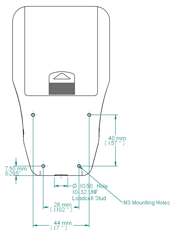
3.2.2 Mounting to a test stand
On the rear of the gauge are 4 x M3 threaded holes, which can be used with the CFG+ Mounting Plate (available as an optional extra) for mounting the gauge to a Mecmesin test stand.
3.2.3 Powering up
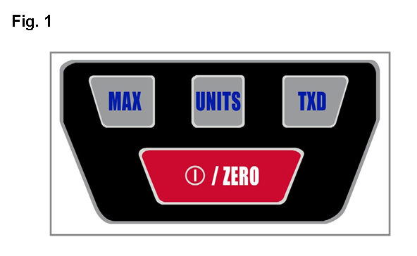
![]() As shown in Fig. 1, the control panel has 4 keys. To power up the gauge press the red and white
As shown in Fig. 1, the control panel has 4 keys. To power up the gauge press the red and white ![]() key. A short self test will run during which the software version number, the currently selected baud rate and the loadcell capacity in newtons are shown. The gauge will then enter the main display mode.
key. A short self test will run during which the software version number, the currently selected baud rate and the loadcell capacity in newtons are shown. The gauge will then enter the main display mode.
After the self test, providing no load has been applied to the instrument, the display will show all zero’s. This is because the gauge zero’s itself during the self test routine.
If a compressive or tensile force is applied via the extension rod to the loadcell, the reading on the display will register the applied force if not in MAX Mode.
3.2.4 Turning off
To turn off the gauge press the ![]() key for at least 2 seconds.
key for at least 2 seconds.
3.3 Basic Functions
3.3.1 Display of Tension/Compression
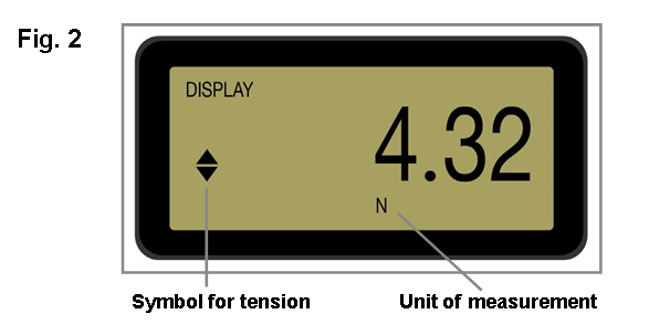
Tensile forces ![]() are displayed on the CFG+ and recognised by the symbol (See Fig. 2).
are displayed on the CFG+ and recognised by the symbol (See Fig. 2).
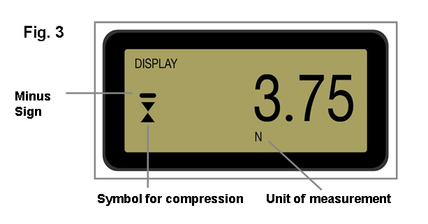
Compressive forces ![]() are displayed on the CFG+ and recognised by the symbol (See Fig. 3).
are displayed on the CFG+ and recognised by the symbol (See Fig. 3).
3.3.2 Zeroing the gauge
During the operation of the gauge it is often necessary to zero the display - e.g. when you wish to tare out the weight of an accessory that you do not want to become part of the measured reading. Press and release the ZERO key.
When the gauge is in the process of zeroing itself a row of segments on the top and bottom of the display will be seen to alternately blink once. When this is completed the display will read zero. This function will not be performed if the gauge is in an overloaded state.
3.3.3 Changing the unit of measurement
You can choose from the following units of measurement depending on the capacity of the gauge: newtons (N), kilogram-force (kg), millinewtons (mN), gram-force (g), ounce-force (oz), pound-force (lb) or kilonewtons (kN).
To change the display units press and release the UNITS key. Each successive key press will select the next available units until the gauge returns to its original setting.
The CFG+ automatically converts readings as new units of measurement are selected.
3.3.4 Max (peak) readings
The gauge detects and stores maximum (peak) force in both compressive and tensile directions.
Peak capture rate is 500Hz
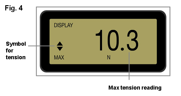
3.3.5 Max Tension
Press the MAX key. The display will show the word MAX together with the highest tensile ![]() force (See Fig. 4).
force (See Fig. 4).
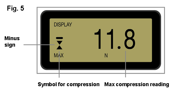
3.3.6 Max Compression
Press the MAX key. The display will show the word MAX together with the highest compressive ![]() force (See Fig. 5).
force (See Fig. 5).
3.3.7 Data Output
The CFG+ has RS232 output. It is possible to transmit the displayed reading to peripheral devices (e.g. PC, printer) by pressing and releasing the TXD key.
Displayed readings can also be requested individually from a PC via the RS232 interface by sending a “?” (ascii D63 [3fh]) character.
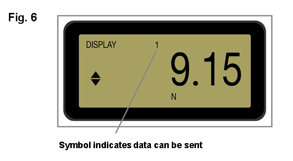
For sending a continuous data stream to a PC, press and hold the TXD key for 2 seconds and release. A ‘1’ will now appear in the display to indicate that data can now be sent (See Fig. 6). To stop sending data, simply press and release the TXD key, at which point a ‘1’ will disappear from the display.
CFG+ uses:
- 9600 or 115200 Baud
- 8 data bits
- 1 start bit
- 1 stop bit no parity
A data cable is available as an optional extra to connect your gauge to peripheral devices
The continuous data stream rate is 100Hz at 9600 Baud and 250Hz at 115200 Baud
Please note that the continuous data stream only starts when approximately 2% of the rated capacity of the gauge is reached.
3.3.8 Remote key press from PC
Hold down the Ctrl key on the keyboard and press:
a to simulate pressing the TXD key*
b to simulate pressing the UNITS key
c to simulate pressing the MAX key
e to simulate pressing the ZERO key
Note that the continuous transmission mode cannot be entered via this method.
3.4 Optional Settings through Dual Function keys
3.4.1 Baud Rate
Holding down the TXD key whilst turning on the gauge will toggle between baud rates of 9600 and 115200. If the baud rate is being toggled, when powered up the gauge will display either 9600 or 115.2 between displaying the software version number and the loadcell capacity. The baud rate setting will be stored in memory and remembered when the gauge is turned off.
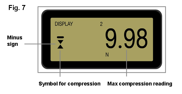
3.4.2 Removing the minus sign during data transmission
Holding down the MAX key while turning the gauge on will enable or disable sending a minus sign with RS232 transmission. If the ‘transmit sign’ function is enabled then ‘2’ is displayed in the top row of the display (See Fig. 7). This setting is stored in the memory and is remembered when the gauge is powered down.
To conserve battery power the gauge constantly keeps a record of time elapsed since the last key press. If this function is not disabled and the low battery symbol is not showing, the gauge will power down after approximately five minutes has elapsed since the last key press, the last load change greater than 2% or the last recurrence of RS-232 communication.
3.4.3 Auto-off
![]() If the gauge is being used for a long test the user may wish to disable the auto-off function. The auto-off function can be disabled when powering up the gauge by holding down the
If the gauge is being used for a long test the user may wish to disable the auto-off function. The auto-off function can be disabled when powering up the gauge by holding down the ![]() until the display shows ‘No Ao’.
until the display shows ‘No Ao’.
3.4.4 Overload
Do not overload the loadcell, as this can cause irreparable damage.
Forces greater than 120% of full-scale will show an ‘-OL-‘ symbol and the corresponding tension or compression symbols on the display. If the display shows ‘OL’ (without dashes) in either of the two max modes, the loadcell is not currently in overloaded state but has been overloaded at least once since the last ZERO operation.
An instrument showing an overload condition cannot be relied upon to provide accurate, repeatable measurement - consult your supplier.
3.4.5 Overload counters
If you suspect that the gauge has been subjected to overloading this can be verified by pressing the UNITS key while turning on the gauge. This will first display the number of overloads in tension, press UNITS key again to see the number of overloads in compression. Press UNITS key once more to allow the gauge to resume powering up.
Removing recorded overloads can only be undertaken by Mecmesin or an approved distributor.
Should the instrument have sustained a catastrophic overload the symbol ‘OL’ will be permanently displayed and the instrument must be returned to Mecmesin or an approved Mecmesin distributor for repair.
3.4.6 Display messages
| ‘-OL-‘ |
Overload - More than 120% of full scale load is currently being applied to the transducer |
| ‘OL’ |
Overload - The peak force reading was applied to the loadcell in excess of 120% of full-scale |
| ‘t-ERR’ |
Tare Error - The zero function was performed while the transducer was in an overloaded state |
| ‘No Ao’ |
No Auto off - Automatic power-off is disabled |
| ‘C-dEF’ |
Calibration default - Invalid calibration data; please notify Mecmesin or an authorised representative for calibration |
3.5 RS232 Commands Table: Configuration
It is possible to remotely read/configure the settings of your CFG+ by sending the following RS232 command characters:
|
Character in ASCII |
Decimal |
Hexadecimal |
Function |
|
M |
77 |
0x4D |
Current mode |
|
U |
85 |
0x55 |
Current units |
|
C |
67 |
0x43 |
Loadcell capacity in newtons |
|
? |
63 |
0x3F |
Transmit the current reading |
|
@ |
64 |
0x40 |
Configuration Status Request |
|
* |
42 |
0x2A |
Toggle Continuous Transmit Mode |
|
r |
114 |
0x72 |
Normal Screen (Non max) |
|
t |
116 |
0x74 |
Max Tension Screen |
|
u |
117 |
0x75 |
Max Compression Screen |
|
a |
97 |
0x61 |
Change Units to mN |
|
b |
98 |
0x62 |
Change Units to N |
|
c |
99 |
0x63 |
Change Units to kN |
|
d |
100 |
0x64 |
Change Units to gf |
|
e |
101 |
0x65 |
Change Units to kgf |
|
f |
102 |
0x66 |
Change Units to ozf |
|
g |
103 |
0x67 |
Change Units to lbf |
|
CTRL a |
1 |
0x01 |
Simulates the TXD key |
|
CTRL b |
2 |
0x02 |
Simulates the UNITS key |
|
CTRL c |
3 |
0x03 |
Simulates the MAX key |
| CTRL e | 5 | 0x05 | Simulates the ZERO key (to ZERO a load reading, not turn the gauge off) |
| CTRL o | 15 | 0x0F |
Turns the gauge off |
3.6 RS232 Command Responses: Information
It is possible to remotely interrogate your CFG+ by sending the following RS232 commands. This will inform you which settings are currently configured.
3.6.1 Command: M
|
Response |
CFG+ Display Mode |
|
Normal |
Normal Mode |
|
MaxC |
Max Compression |
|
MaxT |
Max Tension |
3.6.2 Command: U
|
Response |
|
mN |
|
kN |
|
N |
|
gf |
|
kgf |
|
ozf |
|
lbf |
3.6.3 Command: C
The loadcell size in N
Note: ‘xxxx’ will be transmitted if the loadcell is not calibrated, or has a serious fault. Contact Mecmesin or your supplier.
3.6.4 Command: @
You will receive the following information listing:
|
Response |
Explanation of Response |
|
Compact+ |
Gauge Type |
|
50, 100, 200, 500 or ‘xxxx’ if the gauge is uncalibrated |
Loadcell size in N |
|
V01 |
Version number |
|
Normal, MaxT or MaxC |
Mode of operation |
|
mN, kN, N, gf, kgf, ozf or lbf |
Units of operation |
3.7 CFG+ Specifications
3.7.1 Range & Resolution
|
Model no: |
N |
kgf |
lbf |
|
CFG+ 50 |
50 x 0.05 |
5 x 0.005 |
11 x 0.01 |
|
CFG+ 100 |
100 x 0.1 |
10 x 0.01 |
22 x 0.02 |
|
CFG+ 200 |
200 x 0.2 |
20 x 0.02 |
44 x 0.05 |
|
CFG+ 500 |
500 x 0.5 |
50 x 0.05 |
110 x 0.1 |
3.7.2 Accuracy
±0.5% of full-scale
Calibration temperature: 20°C ±2°C
Operating temperature: 10°C - 35°C
Temperature shift at zero load: ±0.09% of full-scale/°C
3.7.3 Output
| RS232-C |
9600 or 115200 Baud 8 data bits, 1 start bit, 1 stop bit, no parity |
3.7.4 Optional Extras
| AC Power Adaptor |
A 6V - 9V AC-DC power adaptor (fitted with a 1.3mm DC power plug with +6V - +9V DC on the centre conductor), can be plugged into the right hand side of the gauge. Note: Using an incorrect power adaptor can damage the gauge. |
| CFG+ Mounting Plate |
Enables the CFG+ to be mounted to a Mecmesin test stand. |
| Cable CFG+ to RS232 |
An interface cable for connecting your CFG+ to peripheral devices |
| Emperor™ Lite |
Expand the functionality of the CFG+ with Emperor™ Lite data acquisition and plotting software. Analyse test results and view data in graphical format. |
Consult your local distributor to buy any of the above items or please see the website: www.mecmesin.com
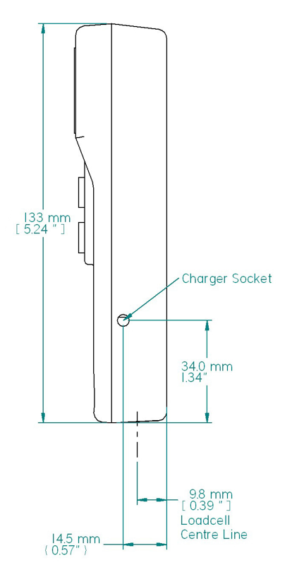
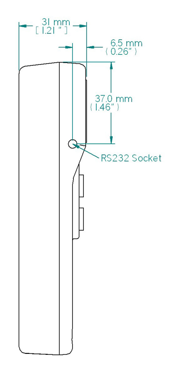
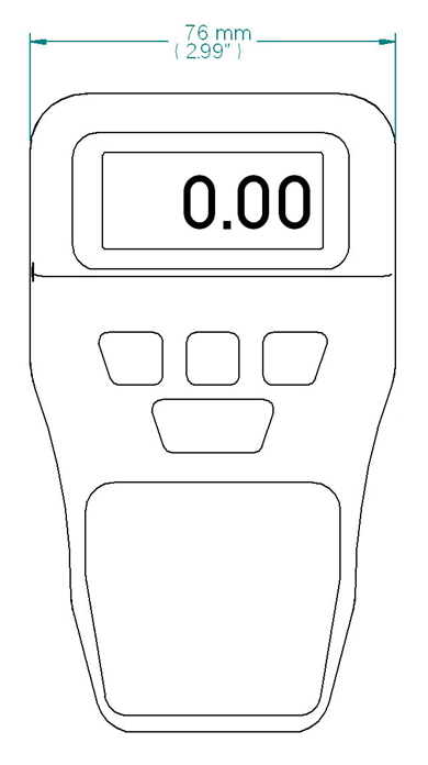
3.8 Dimensions (in Millimetres)
3.8.1 Front View
3.8.2 Rear View
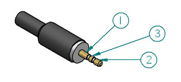
|
Pin Out: |
|
|
1 |
Ground |
|
2 |
RS-232 Transmit |
|
3 |
RS-232 Receive |
Allocation for the pins on the 3-pin connector for RS-232 communication.
3.8.3 Side Views