1 OmniTest 10/25/50 twin column test system user manual
2 Scope
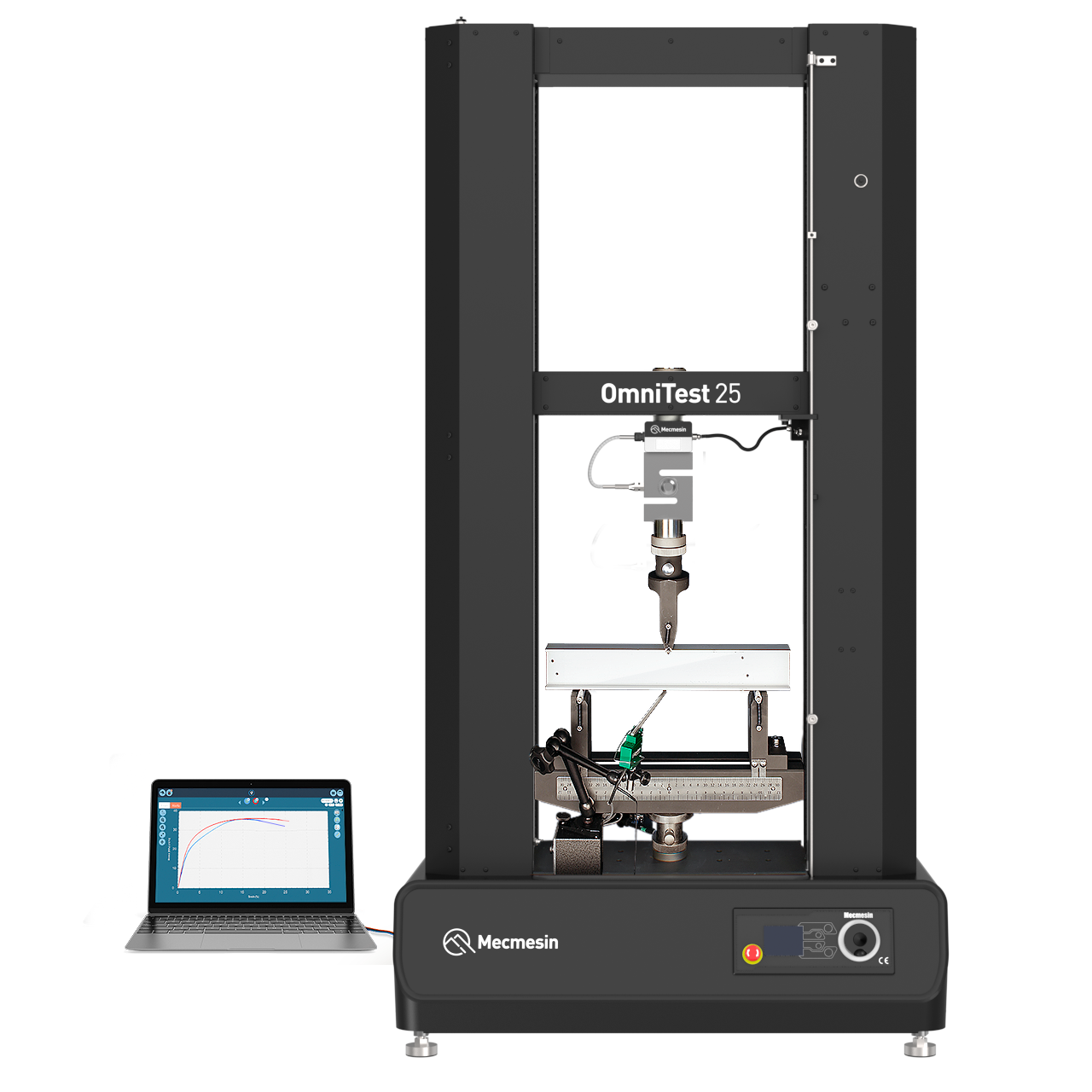
This reference manual covers the operation of an OmniTest Twin Column force test stand (Mk1 and Mk2), intended for use with Mecmesin enhanced load sensors (ELS), extensometer devices and other Mecmesin accessories. Operation of additional accessories is covered in separate documentation.
The following manuals may aid you in the use of your test stand:
- Guide to Safe Use of Mains Powered Test stands (Part: 431-398)
- VectorPro™ for OmniTest and dVu Test Stands (Part: 431-955)
- Long Travel Extensometer Installation Guide (Part: 431-957)
3 Important
It is essential that you familiarise yourself with the contents of this Manual and the separate Guide to Safe Use of Mains Powered Test Stands (Part: 431-398) before attempting to operate your OmniTest twin column test stand.
3.1 User manual icons
Throughout this manual, the icons shown below are used to identify important health and safety information as well as additional installation/operation guidance. Do not proceed until each individual message is read and thoroughly understood.
3.1.1 Warning
3.1.2 Caution
3.1.3 Information
- 1 OmniTest 10/25/50 twin column test system user manual
- 2 Scope
- 3 Important
- 4 Items supplied with your test stand
- 5 OmniTest Twin Column System Diagram
- 6 Initial setup
- 7 Initial setup
- 7.1 Mains power supply: OmniTest 10/25/50 Mk2 (Black)
- 7.2 Mains power supply: OmniTest 10/25/50 Mk1 (Blue)
- 7.3 Enhanced Load Sensor (ELS)
- 7.4 Attaching the ELS to your test stand
- 7.5 Connecting an ELS to the test stand
- 7.6 Connecting the OmniTest twin column to a PC or console
- 7.7 Cable management
- 7.8 Updating test stand firmware using Vector Instrument Programmer (VIP)
- 7.9 Attaching grips and fixtures
- 7.10 Setting the Limit Stops
- 7.11 Test stand states
- 8 Front panel controls
- 9 Automatic ELS firmware update
- 10 Settings
- 11 Connectors Panel
- 12 Specification
- 13 OmniTest twin column dimensions
- 14 Declarations of Conformity
4 Items supplied with your test stand
When ordering your OmniTest Twin Column test stand you will be supplied with the following parts:
| Item | Quantity |
|---|---|
| OmniTest twin column test stand | 1 |
| Mains power cable | 1 |
| External transformer (110-120V - 220-240V) [supplied for regions with 110-120V mains power] | 1 |
| Document: A Guide To Safe Use Of Mecmesin Mains Powered Test Systems | 1 |
| Online manual information card | 1 |
Accompanying VectorPro™ software is available to download online from: https://downloads.vectorpro.cloud.
4.1 Accessories available
For a full range of enhanced load sensors (ELS), extensometers and accessories, please visit Mecmesin.com or contact your local distributor (www.mecmesin.com/distributors).
- For connection of the stand to your computer system a Mecmesin supplied 2m USB B to USB A cable communications cable is required (Part: 351-093).
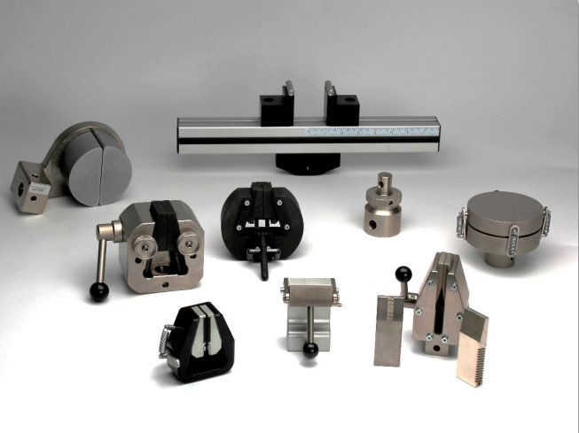
Here you can see some of the grips and fixtures that are available.
5 OmniTest Twin Column System Diagram
5.1 Front View
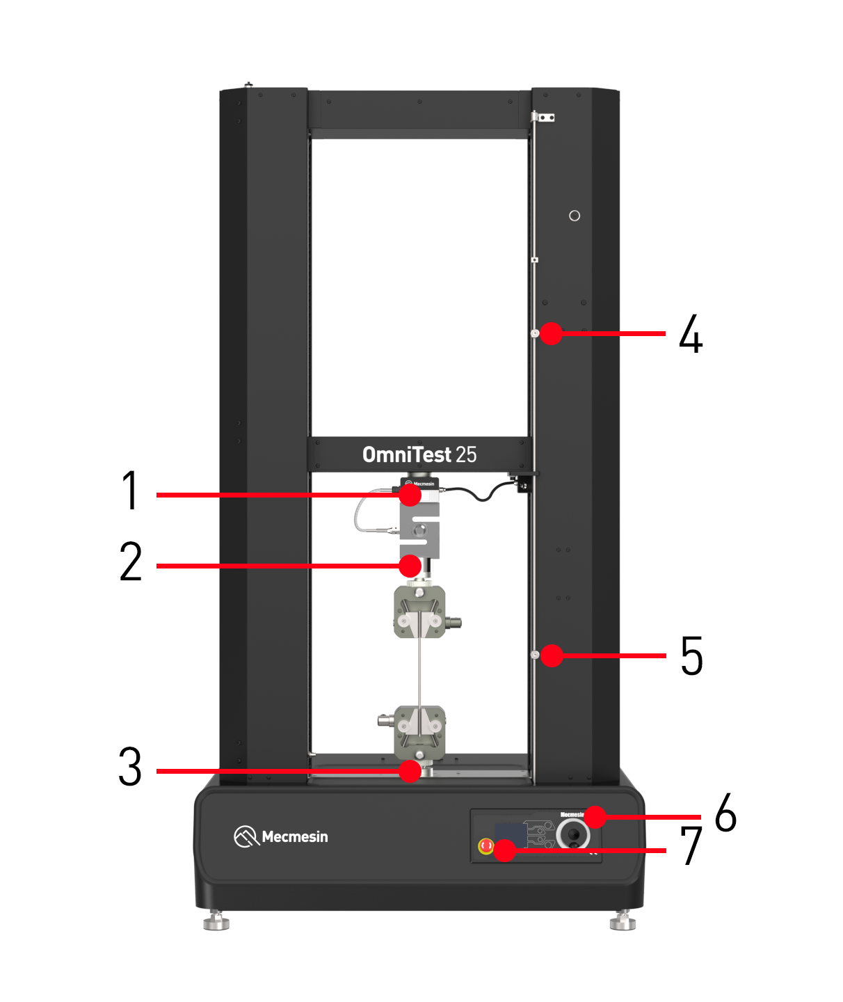
| 1 | ELS loadcell mounted through crosshead |
| 2 | Upper QC mounting adaptor (QC20 'type C', or QC32 'type L') |
| 3 | Lower QC mounting adaptor (QC20 'type C', or QC32 'type L') |
| 4 | Upper adjustable safety limit switch |
| 5 | Lower adjustable safety limit switch |
| 6 | Multi-function scroll wheel and menu selection button |
| 7 | Emergency stop button |
5.2 Side View
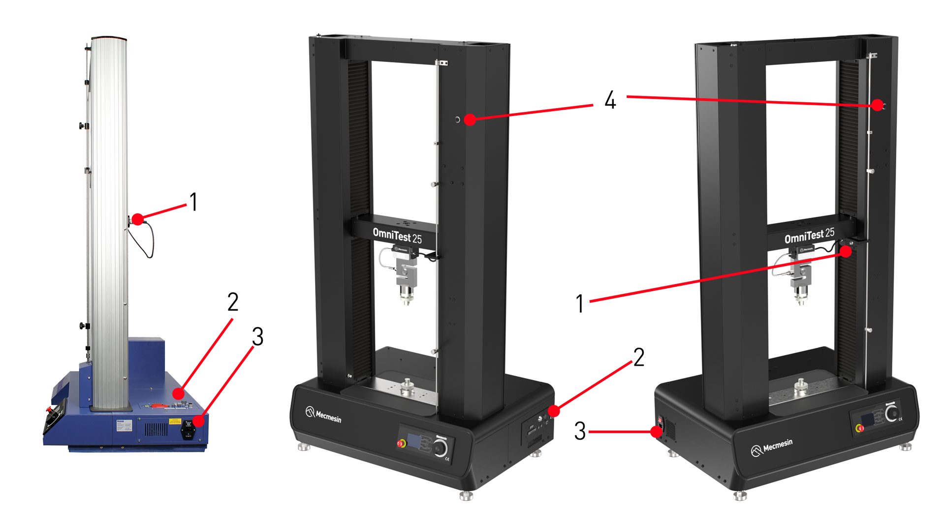
| 1 | ELS loadcell connection to OmniTest |
| 2 | Connectors panel |
| 3 | Mains input socket and power switch |
| 4 | Interlock port (OmniTest 10/25/50 Mk2 (Black)) |
6 Initial setup
6.1 Unpacking the Stand
When you first receive the stand please check that there is no obvious damage to the packaging.
We strongly recommend that the packaging is retained, as this can be useful if the machine needs to be returned for calibration or shipped between sites.
Section 1 lists items that should be included with your test stand. Please contact Mecmesin or your authorised distributor if any items are missing or damaged.
6.2 Moving the Test Stand
6.3 Environment Conditions
In line with BS EN 61010-1 it is recommended that your Mecmesin OmniTest Twin Column test stand is operated in an environment that matches the following conditions:
- Indoor use only, recommended to be operated in a lab environment
- Altitude up to 2 000 m
- Temperature range between 10 °C to 40 °C. Please note that the instrument should not be used for long durations at higher temperatures
- The maximum relative humidity is 80 % for temperatures up to 31 °C decreasing linearly to 50 % at 40 °C. It is crucial that the surrounding environment does not cause water to form on the device.
- Mains supply voltage fluctuations up to a maximum of ±10 % of the nominal voltage.
- The environments should also take considerations of excessive dust or metal particulates as ingress of these into the device can cause damage to the system.
7 Initial setup
7.1 Mains power supply: OmniTest 10/25/50 Mk2 (Black)
Please consult a qualified electrician if you are unsure of your mains power supply/out.
7.1.1 Regions with 220-240 V AC (50-60 Hz) mains power
As standard, the OmniTest 10/25/50 Mk2 (Black) test stand is configured for a 220-240 V AC mains power supply.
If a test stand is being relocated to a region with a 110-120 V AC mains power supply, please see the section below (Regions with a 110-120 V AC (50-60 Hz) mains power) for further information.
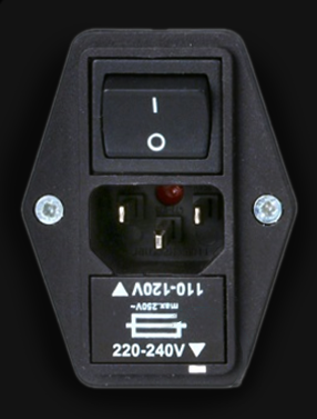
7.1.2 Regions with 110-120 V AC (50-60 Hz) mains power
Mecmesin supplies as standard an external transformer (Part: 164-366) for connecting the test stand to a 110-120 V AC mains power supply, for regions such as the USA and Canada.

| 1 | External transformer step-up voltage converter* |
| 2 | Power indicator |
| 3 | Power on/off switch |
| 4 | Power outlet (220-240 V) - connect this outlet to test stand with supplied power cable. |
| 5 | Mains power supply input - connect this input to the mains power supply with supplied power cable. |
| 6 | Input voltage seelction - please refer to the instruction booklet provided with the external transformer. |
*Images of the external transformer are representative and the supplied equipment may differ in appearance. Please refer to the instruction booklet provided with the external transformer for further information.
The external transformer converter provides the step up in voltage from 110-120 V AC to 220-240 V AC required by the test stand.
The test stand fuse housing of the OmniTest 10/25/50 Mk2 (Black) test stand must not be changed from 220-240 V AC orientation when used with the external transformer for a 110-120 V AC mains power supply.
7.2 Mains power supply: OmniTest 10/25/50 Mk1 (Blue)
The OmniTest 10/25/50 Mk1 (Blue) test stands can be used on 110–120 and 220–240 V AC 50-60 Hz supplies. The rear fuse carrier will be set for your local requirement but is reversible, so should you replace a fuse, the correct local voltage must be selected.
The voltage that is selected is indicated by which arrow is pointing to the white line located at the bottom of the device, as shown below (set to 220-240 V AC).
7.3 Enhanced Load Sensor (ELS)
Enhanced Load Sensors (ELS) are smart devices used to capture load readings for OmniTest twin column test stands. All calibration information is held on the individual loadcell meaning they can be swapped from system to system and the calibration will follow with no input required.
ELS loadcells are available in a range of sizes, capacities, and designs to suit your test requirements. The 'Specifications' section of this document details capture rate and accuracy.
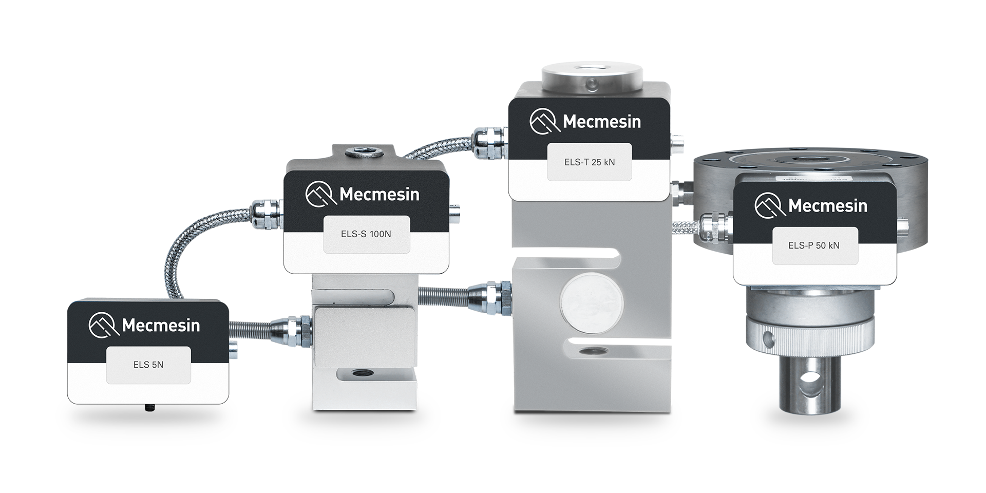
The image above shows a selection of Enhanced Load Sensors (ELS). Some ELS devices shown may not be compatible with twin column test stands. Contact Mecmesin technical support or your local Mecmesin distributor for further information.
7.4 Attaching the ELS to your test stand
7.4.1 ELS loadcells (up to 25 kN)
Loadcells can be very heavy and irregular in shape. Mishandling an loadcell can lead to personal injury or damage to the equipment. Please follow local safety guidelines and procedures when manually handling heavy or irregular shaped items.
The OmniTest twin column uses an M18 bolt that passes through the crosshead and screws into the top of the loadcell.
To fit your ELS to your test stand pass the M18 bolt through the crosshead align the ELS below, use a 14mm Allen key to secure the ELS in place.
It is recommended that one person holds the ELS loadcell in position while another secures the retaining bolt, especially for larger/heavier loadcells.
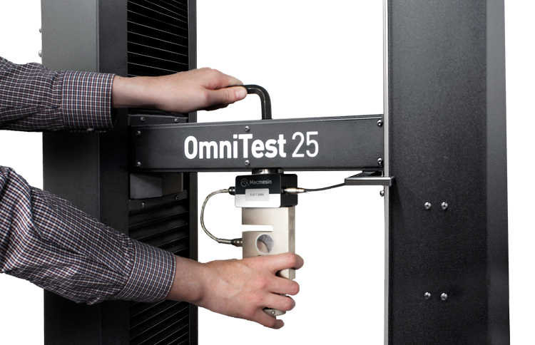
Securing the loadcell with the central M18 bolt
Ensure that attached grips and fixtures do not overload the ELS. If in doubt, please check the weight of any addition grips and fixtures prior to fitting these.
7.4.2 ELS-P 50 kN pancake loadcell
The ELS-P 50 kN pancake loadcell uses an additional method of attachment that should be performed first.

The ELS-P 50 kN pancake loadcell (pictured above) is attached to the crosshead using the eight M8x60 socket cap head bolts and two screws to locate the loadcell's electronics housing.
These screws are 12.9 grade steel with a recommended maximum torque value of 41 N.m. If required the torque values can be checked after first use.
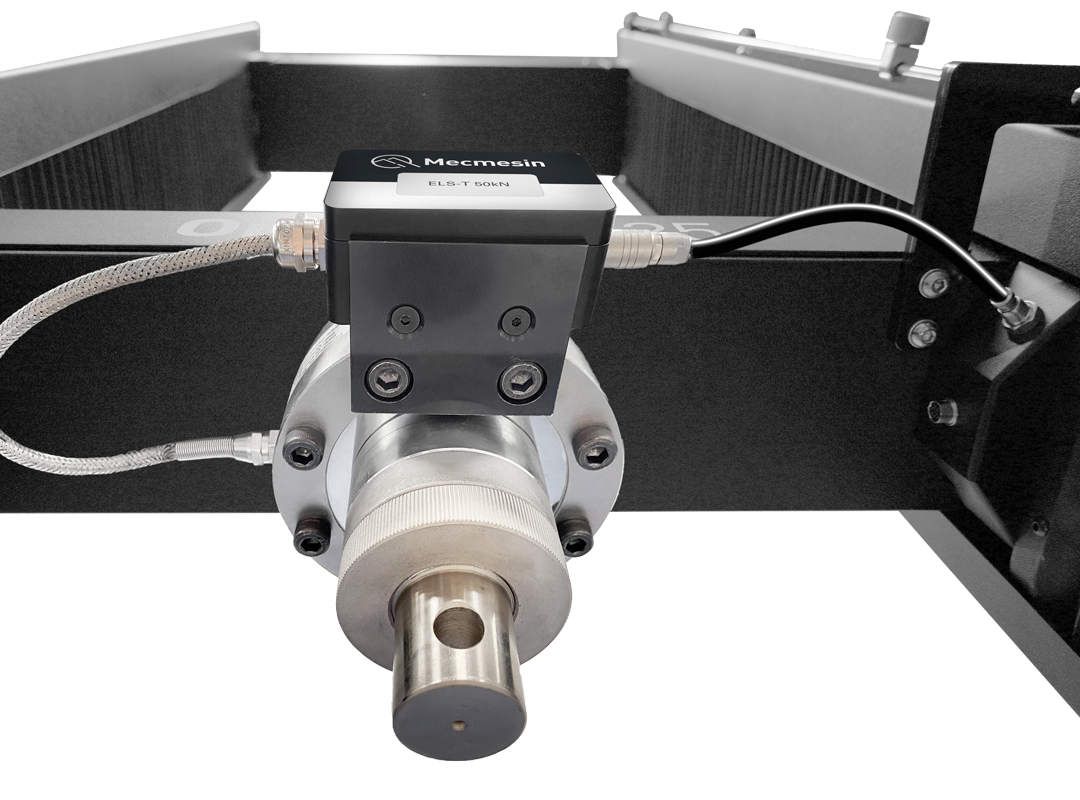
Once attached, pass the M18 bolt through the crosshead into the ELS-P below and use a 14mm Allen key to further secure the loadcell, as with the lower capacity loadcells.
If fitting a QC upper fixture, this will attach from below via an adapter ring with one M18 and 6xM6 cap head bolts.
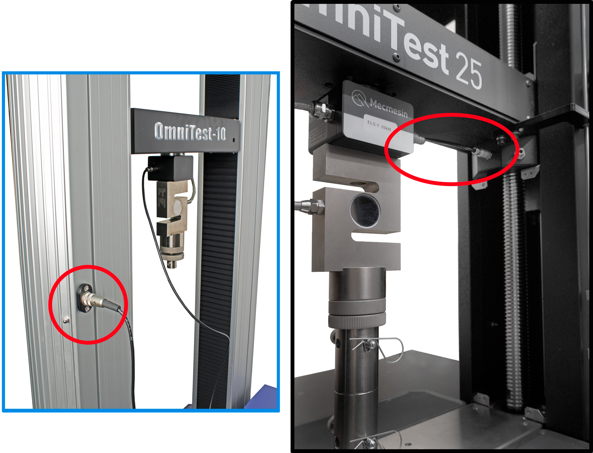
7.5 Connecting an ELS to the test stand
7.5.1 OmniTest 10/25/50 Mk1 (Blue)
To connect your ELS to your OmniTest stand simply plug the Mecmesin ELS to OmniTest cable (Part: 352-275-V01) into both the load cell and the ELS shroud located on the back of the stand.
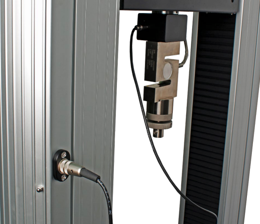
Connecting the ELS to the test stand.
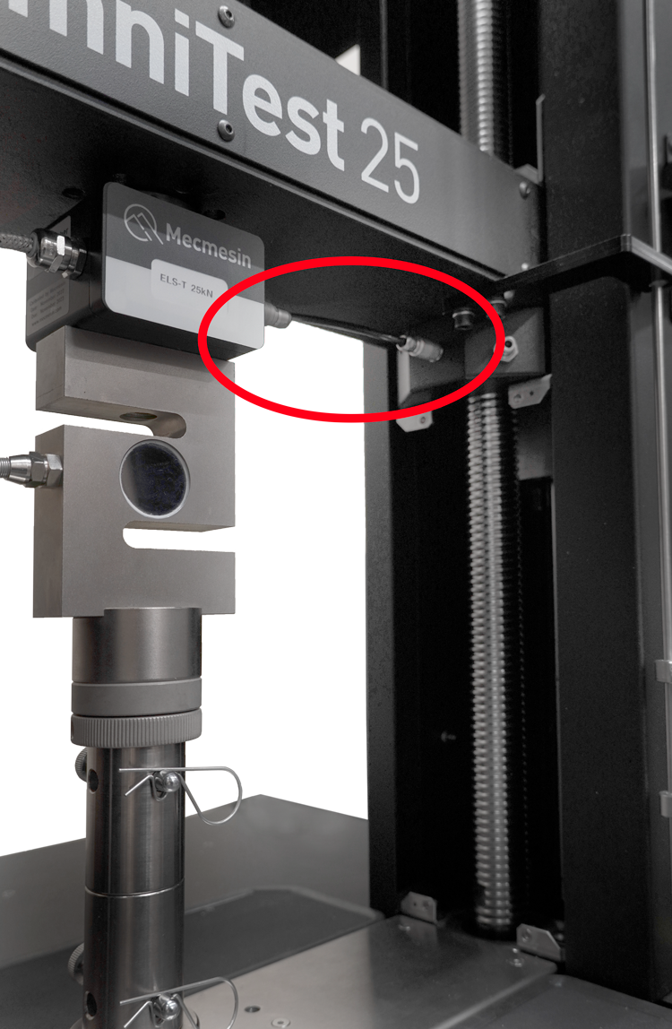
7.5.2 OmniTest 10/25/50 Mk2 (Black)
The ELS is connected to the socket on the moving crosshead as shown below
7.6 Connecting the OmniTest twin column to a PC or console
VectorPro software must be installed on the assigned PC (or console) before connecting the test stand to that device.
To use VectorPro software, you must install the software before connecting your test stand to your PC (or console).
Using the provided data cable (Part: 351-093), insert the USB-B connector into the USB-B port on the rear of the test stand and the USB-A connector into an available USB-A port on your PC (or console).
7.7 Cable management
7.8 Updating test stand firmware using Vector Instrument Programmer (VIP)
From time to time new test stand firmware updates will be released. This could be for several reasons, including introduction of new features, enhancements, or fixing reported issues.
Mecmesin developed the Vector Instrument Programmer (VIP) to simplify the process of updating your Vector-based test stand or instrument. For example, to update your OmniTest test stand to the latest firmware, download the VIP application and ensure the PC that your OmniTest is connected to also has an active internet connection.
You will need a Vector Cloud Services (VCS) account (free of charge).
At the time of writing the following products are compatible with VIP:
- OmniTest
- MultiTest-dV and dV(u)
- Vortex-dV
- VortexPro
- HelixaPro
- Vector instruments (VFG, VFTI and VTG)
7.8.1 Pre-requisites
- Vector Cloud Services account
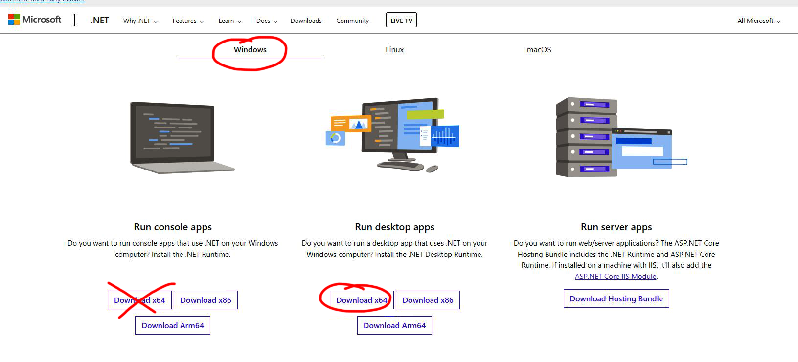
VIP utilises the internet to access Vector Cloud Services (VCS) for the latest firmware release, requiring a Vector Cloud Services (VCS) account. Creating a Vector Cloud Services (VCS) account is straightforward requiring only a valid email address. No payment or credit card details are required. - .NET runtime 6
Another pre-requisite is for the free Microsoft utility ".NET runtime 6" to be installed. Be sure to install the "Download x64" option in the Windows tab under the "Run desktop apps" option as shown below. The download can be found here https://dotnet.microsoft.com/en-us/download/dotnet/6.0/runtime?cid=getdotnetcore
Vector Instrument Programmer (VIP) is self updating so the installation only needs to be completed once. Updates to VIP are pushed to the app when available.
The app does not automatically create a desktop shortcut. To create a shortcut, locate the VIP executable file at the following location on your PC:
- C:\Program Files (x86)\PPT Group\Vector Instrument Programmer\VectorInstrumentProgrammer.exe
7.8.2 How to use VIP
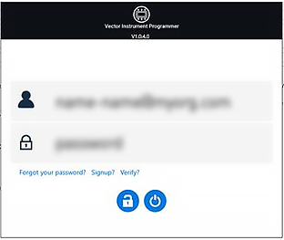 Sign-in using your Vector Cloud Services (VCS) account credentials.
If you don't have an account, you can create one by clicking on 'Signup?' option.
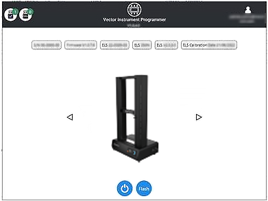 Connect your Vector device to the PC running VIP using the USB data cable supplied with your product. Your device will appear in the app.
If you have more than one device connected (indicated in the top-left corner by the USB icon) you can switch between devices by using the left and right arrows to either side of the device picture.
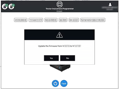 Check for firmware updates for your device by clicking on the 'Flash' button. A popup will appear asking if you want to update along with the currently installed version and the latest available version.
If the version numbers are the same then no action is required and you can select 'No' to return to the home page.
If the version numbers are different then an update is available.
If you want to proceed with the update, select 'Yes' and the application with update the instrument automatically.
A progress bar will display the status of the update and, once the update is complete, your instrument will power back on and the software will go back to the home screen.
Software updates will be published when updates are released in the software section of our support center at www.Mecmesin.com. If you are unsure or if you need help updating your product please contact support@mecmesin.com.
7.9 Attaching grips and fixtures
7.9.1 Lower fixtures
The OmniTest twin column test stand features a base plate with numerous threaded holes, spread symmetrically across its width, as well as fixing points for a standard 20 mm QC adapter. This configuration supports the flexible attachment of a wide variety of accessories.
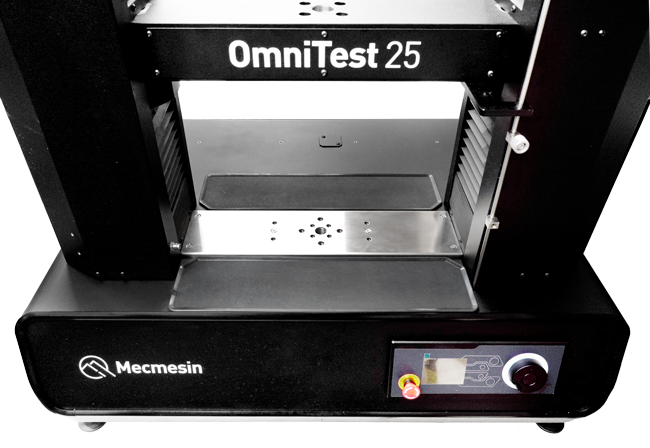
OmniTest twin column base plate (above).
7.9.2 Upper fixtures
Upper fixtures, grips, and accessories are attached directly to the ELS loadcell being used.
Mecmesin LTE-1100 extensometers are available and can be fitted directly to the base plate (above).
7.10 Setting the Limit Stops
Limit Stops help prevent damage to load cells and fixtures by stopping the crosshead movement before the moving fixtures come into contact with static parts of the stand. Their positions are adjusted after the fitting of fixtures and test samples.
There are two manually-set limit stops, located for your convenience, on the front of the OmniTest twin column.
These are set by loosening the thumb-screw, moving the stop to a new position and retightening.
When the crosshead meets a stop, it activates a switch. This will stop the crosshead movement at an upper or lower limit.
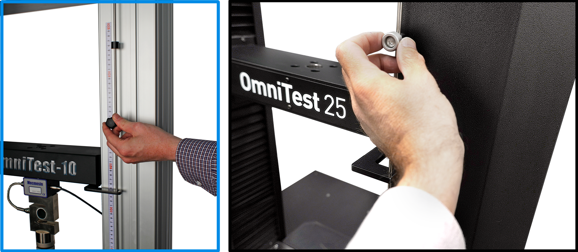
Limit stops on an OmniTest twin column
7.11 Test stand states
The test stand can be in one of five states:
- Test readiness - ready to start, or complete
- Testing – test operation sequence is running
- Stopped - test interrupted or emergency stop pressed
- Jog mode - for jogging or positioning the crosshead manually
- Settings menu – for adjusting your test stands settings
In each state, the selector buttons have functions described by the on-screen icons.
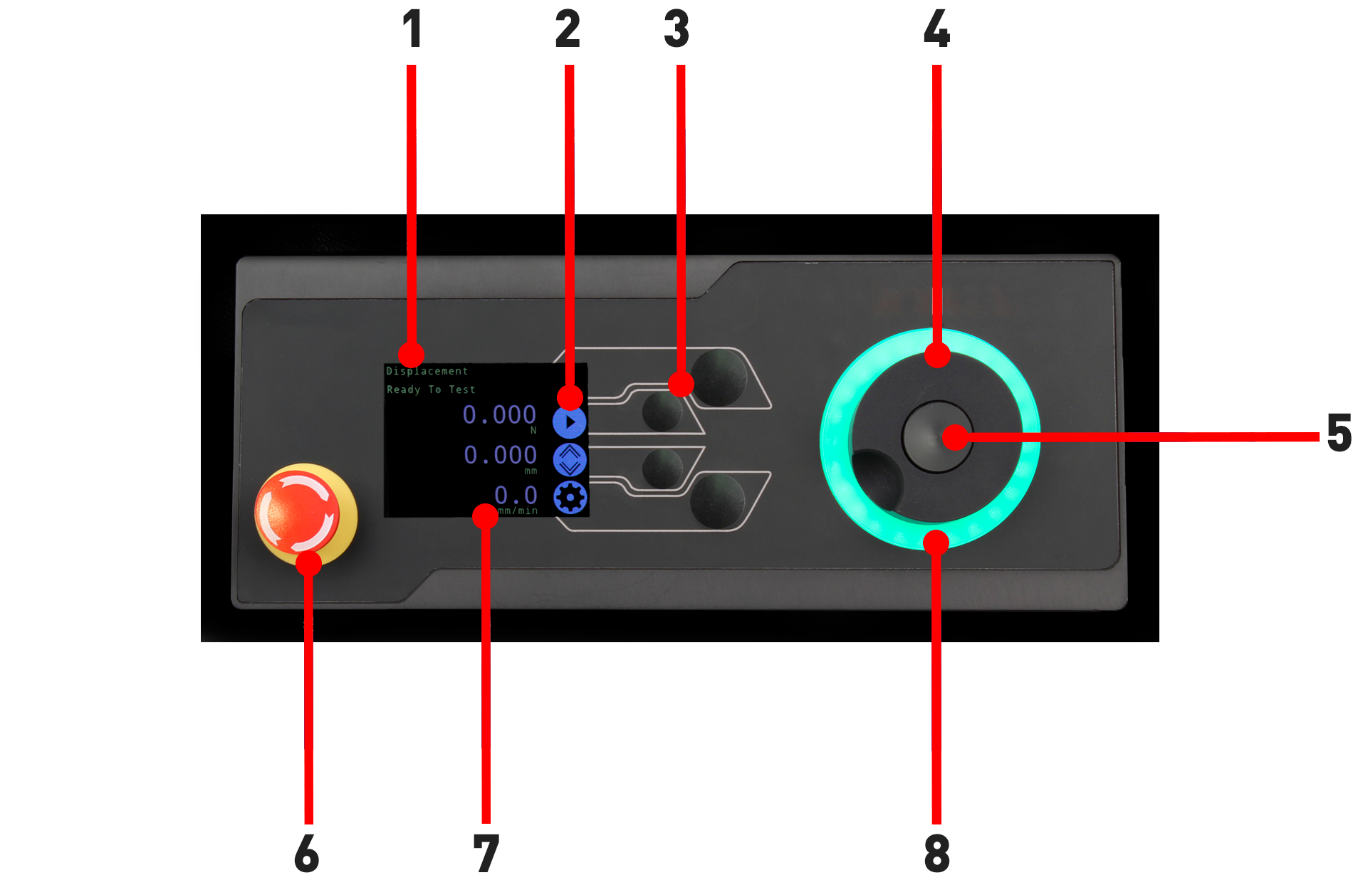
8 Front panel controls
|
1 |
Status messages |
|---|---|
|
2 |
Button functions |
|
3 |
Multi-Function selector buttons |
|
4 |
Multi-function scroll wheel |
|
5 |
Scroll wheel button |
|
6 |
Emergency stop button |
|
7 |
Display |
| 8 | LED indication dial |
8.1 Emergency Stop button
 |
Push the emergency stop button to immediately stop the crosshead movement. Rotate the button to release it and resume crosshead control. If pressed during a test, do not simply restart a test. Ensure any residual force is removed using the test stand’s jog controls before continuing. |
8.2 Multi-function scroll wheel control
8.2.1 Scroll wheel colours
The LED light ring surrounding the scroll wheel shows three colours, indicating three states, these states are:
 |
Green Light Pulsating: Ready to start testing Rotating: Scrolling through a menu |
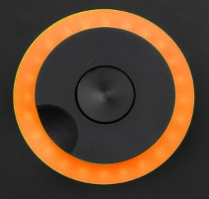 |
Amber Light Static: The current test has completed Rotating: The crosshead is moving |
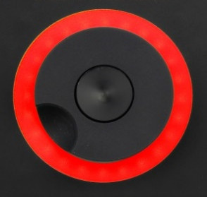 |
Red Light Static: The test has stopped or a limit has been triggered |
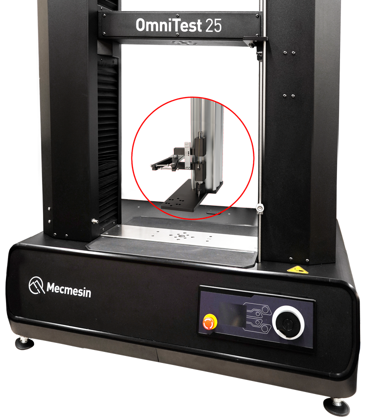
8.2.2 Jog mode
When in jog mode the scroll wheel drives the crosshead directly up (clockwise) or down (anticlockwise). This offers more variable control when compared to the two fixed speed jog control buttons (circled in red below).
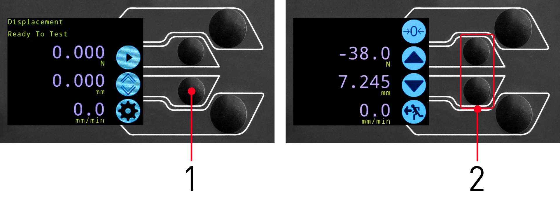
| 1 | Enter jog mode |
|---|---|
| 2 |
Jog keys up and down |
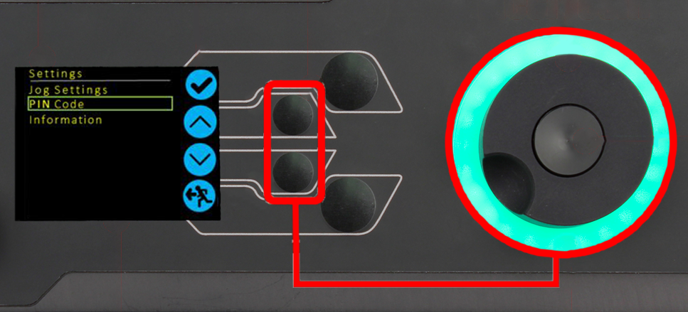
The scroll wheel can also be used as a speed controller. The jog buttons move the crosshead at the set speeds (configured in the ‘Jog Settings’ menu picture below).
Rotating the wheel clockwise whilst holding a jog button will increase the jog speed and rotating the wheel anticlockwise whilst holding a jog button will decrease the speed.
OmniTest twin column test stands also feature a precision jog mode, rotating the scroll wheel while holding the central scroll wheel button moves the test stand at its minimum speed, this is useful when fitting specimens into grips or if precision positional control is required.
8.2.3 Navigational and selection
The scroll wheel can also be used to navigate the menus. When in a selection menu, the scroll wheel cycles through the selections and their values. This is an alternate navigational option to using the up and down arrow buttons.
8.2.4 Central button
The central button is used to confirm a menu selection. It is equivalent to the tick button.
It can also be used to activate fine jog control. Use by rotating the scroll wheel while holding the central scroll button. This drives the test stand at its minimum speed.
8.3 Display panel
The display indicates the stand status, displays live values and is used to configure the test stand settings.
The purposes of the four selection push-buttons are indicated on-screen by an adjacent icon. Below is an image showing a typical example of the on-screen icons in relation to the physical buttons.

| 1 | The top icon is 'Confirm' |
|---|---|
| 2 | The Mid-upper icon is 'Up' |
| 3 | Selection buttons |
| 4 | The Mid-lower icon is 'Down' |
| 5 | The lower icon is 'Back / Exit' |
8.4 Test stand states
The test stand can be in one of five states:
- Pre-Test - ready to start, or complete,
- Testing – test operation sequence is running,
- Test Stop- test interrupted or emergency stop pressed,
- Jog Mode - for jogging or positioning the crosshead manually,
- Settings Menu – for adjusting the test stand settings,
In each state, the selector buttons have functions described by the on-screen icons.
8.5 On-screen icons
On-screen icons vary depending on the current state of the test stand and the menu functions the physical buttons perform at that point. Below are reference tables to help explain the icon definitions.
8.5.1 A: Pre-test
| Icon | Action |
|---|---|
 |
No sensor connected |
 |
Enable jog mode |
 |
Go to settings |
 |
Move to the home position (Set within VectorPro or test start position) |
8.5.2 B: Test Stop
| Icon | Action |
|---|---|
 |
Stop test: This stops the crosshead movement, leaving the stand in a test- ended status. The message is ‘Interrupted: User’ and the Home or exit/return menu buttons are shown. |
|
Emergency stop button pushed: Message: ‘Emergency Stop!!!!’. Remedy the situation causing the required stop, then release the emergency stop to regain control. Note: there is no on-screen icon for the emergency stop. |
 |
Upper limit switch triggered: The crosshead has reached the upper travel limit, as set by the OmniTest limit switches, and stopped. Further travel in this direction is prevented. |
 |
Lower limit switch triggered: The crosshead has reached the lower travel limit, as set by the OmniTest limit switches, and stopped. Further travel in this direction is prevented. |
8.5.3 C: Jog Mode
| Icon | Action |
|---|---|
 |
Zero (tare) all OmniTest readings |
 |
Move the crosshead upward at the set jog speed |
|
Crosshead has reached an upper limit (load signal from a connected gauge, set to Stop, or a limit switch) and stopped |
 |
Move the crosshead downward at the set jog speed |
|
Crosshead has reached a lower limit (load signal from a connected gauge, set to Stop, or a limit switch) and stopped |
 |
Exit jog mode |
8.5.4 D: Settings Menu
| Icon | Action |
|---|---|
 |
Confirm selection (or press the scroll wheel button) |
 |
Navigate ‘up’ a menu selection or value (or turn the wheel clockwise) |
 |
Navigate ‘down’ a menu selection or value (or turn the wheel anticlockwise) |
 |
Exit settings screen |
9 Automatic ELS firmware update
All OmniTest twin column test stands with firmware 3.1.0.0 and above have the ability to update the firmware of any connected ELS device.
This feature is seamlessly managed through the front panel and ensures that the latest firmware is on the ELS devices.
To start the update connect the ELS to the test stand and switch the test stand on.

The test stand front control panel (as pictured above) will be presented if a firmware update is available for the connected ELS device.
The new ‘Stored’ firmware is listed at the top of the display and the current ELS firmware is displayed below. In this example (as pictured above) the ELS current firmware is 1.0.8.000, starting the update will flash the device to version 2.1.000.
If more than one ELS is connected (load cell and a short analogue extensometer) the additional devices will be listed. To start the update of the first ELS device press the ‘tick’ icon.
If you press the ‘Cross’ icon the upgrade can be started manually by opening the information screen located within the settings menu and scrolling to the ELS firmware version. This will have a ‘*’ next to it, pressing the ‘tick’ icon will open the firmware upgrade screen pictured above.

The flashing of the device is carried out automatically and progresses through several stages.
In the image above initial programming is taking place. The progress can be monitored using the bar and percentage readout shown onscreen.
It is important that the test stand is not turned off or disconnected during an update. An interruption to the power or disconnection of the ELS during an update could lead to irreversible damage.

Once the firmware update process reaches '100%', the display will indicate that the firmware update has been successful.
The display panel will then prompt for the update of the next device currently connected or the return to the start screen if no additional devices are connected.
10 Settings
All settings are made by moving the selection marker to the required item or digit and confirming with the tick button or using the central scroll wheel button.
10.1 Jog settings
Within the jog settings menu, you can configure the jog speed and force limits while in jog mode.
Below is a detailed breakdown of each setting and the options available for each setting.
| Setting | Action | Range |
| Up Speed | Configure the jog speed in an upward motion |
0.050 to 1200 mm/min 0.002 to 47.24 inch/min |
| Down Speed | Configure the jog speed in a downward motion |
0.050 to 1200 mm/min 0.002 to 47.24 inch/min |
| Tension Limit | Configure the tensile force limit for jog operations |
Up to 2500 N Up to 562 lbf |
| Compression Limit | Configure the compressive force limit for jog operations |
Up to 2500 N Up to 562 lbf |
10.2 PIN code
Within the PIN code menu, it is possible to set a four-digit number than can be used to lock the menu feature of the test stand. Please note once this has been set you cannot access the menu within the PIN, so it is crucial that you keep a record of this safe.
To remove a PIN code, set the four-digit number to '0000'.
10.3 Pre-load threshold
This menu displays the pre-load threshold as configured by VectorPro™, changes here will be overwritten by VectorPro next time you start a test.
10.4 Information
This screen is used to display key information relating to your OmniTest twin column and connected ELS devices. Here you can see software, hardware and firmware properties as well as the calibration date for the test stand and the number of overloads that have occurred for the current ELS.
11 Connectors Panel
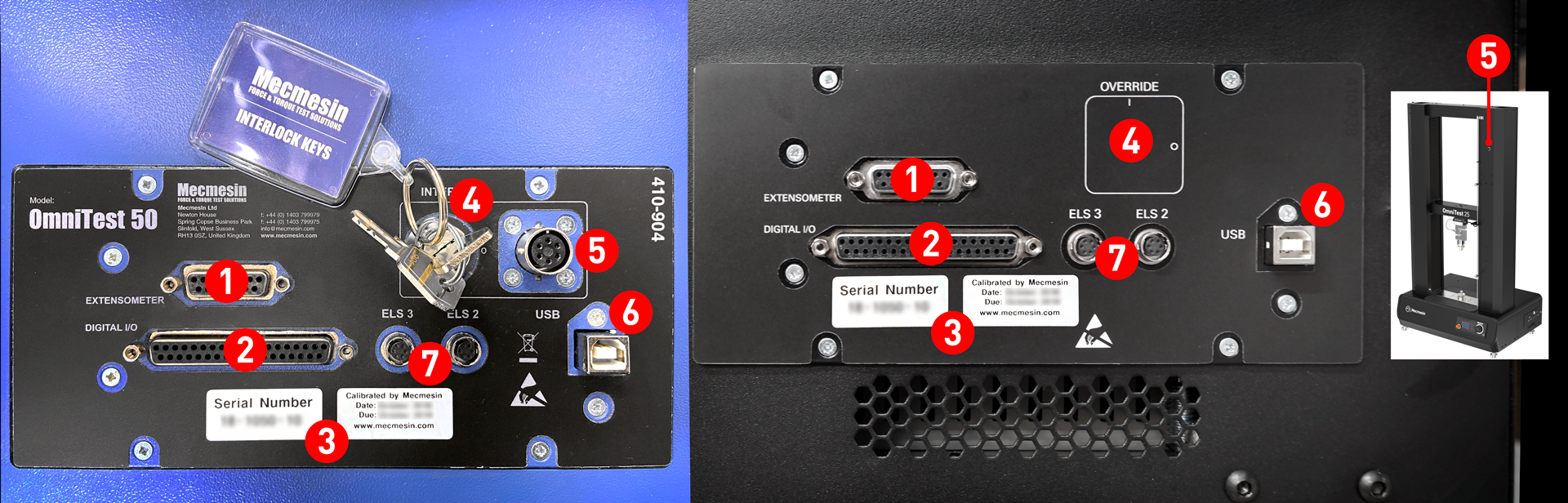
- Extensometer port
- Digital IO port (not currently implemented)
- Calibration date and serial number
- Interlock override switch
- Interlock port
- USB-B Comms port
- ELS 2 and 3 (not currently implemented)
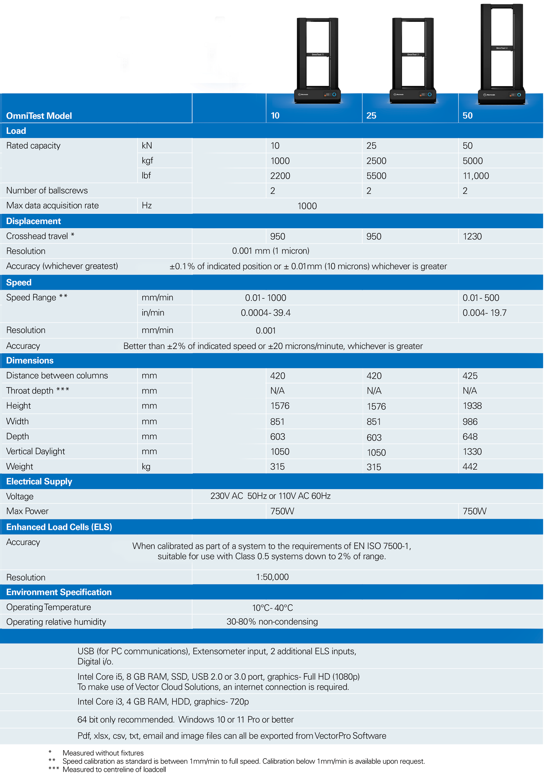
12 Specification
12.1 OmniTest 10/25/50 Mk1 (Blue)
| OmniTest Test Stand | 10 | 25 | 50 | ||
|---|---|---|---|---|---|
| Rated Capacity kN | kN | 10 | 25 | 50 | |
| kgf | 1000 | 2500 | 5000 | ||
| lbf | 2200 | 5500 | 11000 | ||
| Number of Ballscrews | 2 | ||||
| System accuracy | Class 0.5, according to the requirements of BS EN ISO7500 (requires optional onsite UKAS accredited system calibration) | ||||
| Maximum sampling rate | 500 Hz | ||||
| Load holding | Yes | ||||
| Displacement | |||||
| Crosshead Travel | 950 mm (37.4”) | 950 mm (37.4”) | 1100 mm (43.3”) | ||
| Resolution | 1 µm | ||||
| Accuracy | ±0.1% of indicated position or ±10 microns, whichever is greatest | ||||
| Speed | |||||
| Calibrated Speed Range | mm/min | 0.05 to 1000 | 0.05 to 1000* | 0.05 to 400** | |
| in/min | 0.002 to 40 | 0.002 to 40 | 0.002 to 15 | ||
| Speed Resolution | 0.001 mm/min (0.00004 In/min) | ||||
| Accuracy | ±2% of indicated speed or ±20 µ/min whichever is greater | ||||
| Dimensions | |||||
| Height | 1500 mm (59.1”) | 1500 mm (59.1”) | 1931 mm (76”) | ||
| Width | 826 mm (32.5”) | 826 mm (32.5”) | 826 mm (32.5”) | ||
| Depth | 542 mm (21.3”) | 542 mm (21.3”) | 572 mm (22.5”) | ||
| Vertical Daylight | 1140 mm (44.9”) | 1140 mm (44.9”) | 1330 mm (52.4”) | ||
| Distance between columns | 400 mm (15.7”) | 400 mm (15.7”) | 420 mm (16.5”) | ||
| Weight | 140 kg (309 lbs) | 140 kg (309 lbs) | |||
| Electrical Supply | |||||
| Voltage | 230V AC 50Hz or 110V AC 60Hz | ||||
| Maximum Power Requirement | 450 watts | ||||
| Enhanced Load Sensor (ELS) | |||||
| Accuracy | ±0.5% of reading down to 5% of range | ||||
| Sensor Measurement Resolution | >1:25000 filtered from 24 bit | ||||
| Internal Sampling Rate | 20 kHz | ||||
| Environment Specification | |||||
| Operating Temperature | 10°C - 40°C | ||||
| Operating Relative Humidity | Normal Industry and laboratory conditions. 30%-80% (non-condensing) | ||||
* 25 kN - recommended maximum speed = 500 mm/min (20 in/min) above 10 kN
** 50 kN - recommended maximum speed = 250 mm/min (10 in/min) above 25 kN
| Software and communications | ||
| Connectivity | USB port, extensometer input, 3 low voltage additional sensor inputs with future expansion capability | |
| PC requirements | Recommended | Intel Core i5 processor, 8 GB RAM, on USB 2.0 or 3.0 port, SSD hard drive with 10 GB free space, screen resolution 1920x1080 (full HD) |
| Minimum | Intel/AMD dual core processor with 2 GHz or faster clock speed, 4 GB RAM, one USB 2.0 or 3.0 port, hard drive with 10 GB free space, screen resolution 1080x720 | |
| Operating System (OS) | Recommended OS | Windows 10 Pro (64 bit) |
| Compatible OS | Windows 7 or Windows 10 (32 or 64 bit) | |
| Data output | You can export as PDF, XLSX, CSV, TXT, email and image file formats | |
12.2 OmniTest 10/25/50 Mk2 (Black)
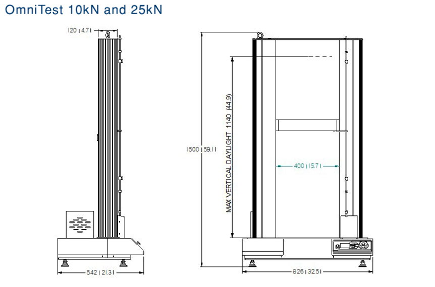
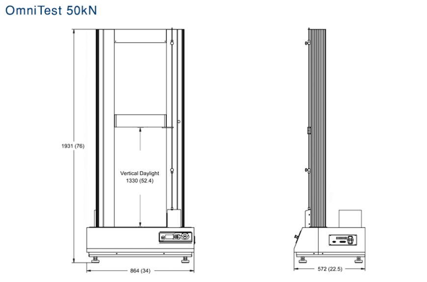
13 OmniTest twin column dimensions
13.1 OmniTest 10/25/50 Mk1 (Blue)
13.2 OmniTest 10/25/50 Mk2 (Black)
13.2.1 OmniTest 10/25 Mk2 (Black)

13.2.2 OmniTest 50 Mk2 (Black)

14 Declarations of Conformity

