
- 1 Introduction
- 2 Before Use
- 3 Operation
- 4 Maintenance
- 4.1 Powering the Gauge
- 4.2 Using the Gauge
- 4.3 Basic Functions
- 4.4 Smart Force & Torque Sensors
- 4.5 Advanced Menu Options
- 4.6 Stand
- 4.7 ALARM
- 4.8 PLC
- 4.9 PASSWORD
- 4.10 FREEZE
- 4.11 % 1st PEAK
- 4.12 AV/TIME
- 4.13 Rate
- 4.14 FOOTSWITCH 1
- 4.15 FOOTSWITCH 2
- 4.16 COMMS
- 4.17 INFORMATION
- 4.18 Calibration
- 4.19 x CONSTANT
- 4.20 MAX LOCK
- 4.21 UNITS LOCK
- 4.22 BACKLIGHT
- 4.23 AUTO OFF
- 4.24 INVERT
- 4.25 DEFAULTS
- 4.26 RS232 Commands Table: Configuration
- 4.27 RS232 Command Responses: Information
- 4.27.1 Command: M
- 4.27.2 Command: U
- 4.27.3 Command: C
- 4.27.4 Command: @
- 4.27.5 STAND ON options
- 4.27.6 ALARM ON options
- 4.27.7 PLC OUTPUT ON options
- 4.27.8 PASSWORD 1 options
- 4.27.9 FREEZE ON options
- 4.27.10 % 1st Peak options
- 4.27.11 AV TIME ON options
- 4.27.12 RATE 1 ON options
- 4.27.13 FOOTSWITCH1 ON options
- 4.27.14 FOOTSWITCH2 ON options
- 4.27.15 COMMS settings
- 4.27.16 X CONST ON options
- 4.27.17 MAX LOCK 1 options
- 4.27.18 UNIT LOCK 1 options
- 4.27.19 BACKLIGHT 1 options
- 4.27.20 AUTO-OFF 1 options
- 4.27.21 INVERT 1 options
- 4.28 Advanced Menu Options Flow Chart Menu Page 1
- 4.29 Advanced Menu Options Flow Chart Menu Page 2
- 4.30 Advanced Menu Options Flow Chart Menu Page 3
- 4.31 DIMENSIONS
- 4.32 AFG SPECIFICATIONS
- 4.33 Communications Cables
1 Introduction
Thank you for choosing Mecmesin’s Advanced Force Gauge (AFG). With correct use and regular re-calibration it will give many years of accurate and reliable service. The Mecmesin AFG is the flagship member of a series of highly versatile display units. By using the latest integrated circuit technology it has been possible to produce an instrument which can be used to measure tensile and compressive forces accurately, whilst being simple to use by the operator. Information contained in this operating manual also applies to the AFG or Advanced Force & Torque Indicator (AFTI) display when used with ‘Smart’ sensors.
2 Before Use
Upon receiving the unit please check that no physical damage has occurred to the packaging material, plastic case or the instrument itself. If any damage is evident please notify Mecmesin immediately.
3 Operation
The most commonly used features, such as displaying force, peak hold, zero and changing of displayed units of measurement can all be done by pressing a single dedicated key on the front panel with grey text - see page 6, Basic Functions.
To configure the advanced features of the gauge, a full menu-driven system is accessible using the keys identified on the front panel with red text - see page 11, Advanced Menu Options. The Advanced Force Gauge (AFG) page 2
4 Maintenance
When cleaning the keypad care must be taken to avoid liquids, especially alcohols, seeping around the edge of the membrane. Therefore, we recommend the use of a lightly dampened cloth to avoid liquid spillage onto the membrane.
4.1 Powering the Gauge
The AFG is supplied with a set of 5 Nickel Metal Hydride AAA rechargeable batteries, which are supplied fully charged to allow use straight from the box. Do not use any other battery charger other than that supplied with the force gauge.
4.1.1 Replacing batteries
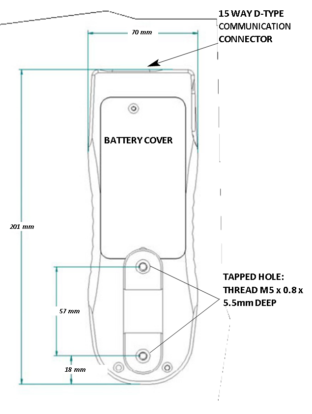
To replace the batteries you must first remove the battery cover on the upper part of the rear of the gauge by removing the 2 retaining screws. Remove the fitted batteries and fit the 5 new batteries in the battery holder ensuring that you observe polarity and the batteries are placed on top of the ‘release tag’ and they will be freed from the spring-loaded contacts.
Refit the battery cover and tighten the 2 retaining screws.
Connect the mains adaptor/charger to the AFG charger socket located at the right hand side of the gauge next to the display and charge the batteries for 14 - 16 hours. Only use the adaptor/charger supplied. A fully charged battery pack will provide approximately 20 hours constant use between charges.
4.1.2 Low battery warning
A low battery symbol will appear in the display approximately 2 minutes before the gauge powers down automatically. See Fig 1.

4.1.3 Mains operation
The AFG can also be powered directly from the mains. This can be achieved with or without the rechargeable batteries being fitted. Connect the mains adaptor/ charger to your mains supply. Only use the adaptor/ charger supplied.
4.1.4 Fitting of alkaline batteries
If rechargeable batteries are fitted, a trickle charge will be applied to the batteries with the display switched on.
The AFG can also be powered by AAA 1.5V alkaline batteries (not supplied). For the fitting of alkaline batteries, follow fitting instructions as per rechargeable batteries above.
Warning: When alkaline batteries are fitted, the mains adaptor/charger must NEVER be connected to the AFG due to the risk of acid leakage which could damage the instrument.
4.1.5 Battery safety information
NEVER:
- Short circuit
- Disassemble or deform cells
- Heat or incinerate
- Immerse in water
- Solder anything to the battery terminals
- Reverse individual cell polarity
- Use alternative chargers other than those supplied by Mecmesin
- Use replacement parts other than those supplied by Mecmesin
Never dispose of batteries with ‘normal’ refuse. Contact your local Environmental Authority to determine the location of your appropriate disposal facility.
4.2 Using the Gauge
4.2.1 Fitting accessories
All AFG instruments are supplied with a short extension rod (30mm long). This fits directly onto the loadcell mounted in the bottom of the AFG. When attaching accessories to the gauge always use the extension rod. It comes supplied with a thumb wheel to control the orientation of any accessory fitted. When fitting the extension rod ensure that it is screwed finger-tight only. Excessive torque can damage the loadcell. Your chosen grip can now be fitted to the extension rod which has a 10-32UNF male thread (10-500N), 5/16”UNC (1000-2500N).
4.2.2 Mounting to a test stand
On the rear of the gauge there are two M5 threaded holes, which can be used for mounting the gauge to a Mecmesin test stand.
Each Mecmesin test stand is supplied with a dedicated ‘dovetailed mounting bracket’ and screws for this purpose.
If you wish to mount to another type of stand, ensure that the screws used are threaded into the gauge to a maximum depth of 12mm. If screws are fitted beyond this depth, damage to the internal PCB or loadcell may occur.
4.2.3 Powering up
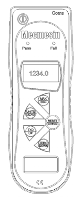
As shown in Fig 2 the control panel has 5 Function keys plus an On/Off key:

To power up the gauge press the red ![]() key. A short self test runs during which the display will show the model and capacity in newtons.
key. A short self test runs during which the display will show the model and capacity in newtons.


Note: The current version of the gauge’s operating software appears in the bottom left corner of the start-up screen. This may have been updated, however the manual supplied with your AFG remains valid.
After the self test (if the ‘X CONSTANT’ is used, its value will be displayed at this point) providing no load has been applied to the instrument, the display will show all zeros. This is because the gauge re-zeros itself during the self test routine.
Please note that an AFG measuring very low forces may not show zero if it is moved during the self test routine. Once it is properly mounted and zeroed the reading will be stable.
If a compressive or tensile force is applied to the sensor probe (bottom of AFG), the reading on the display will register the applied force.
Do not overload the loadcell, as this could cause irreparable damage.
Forces greater than 120% of full-scale will produce an audible beep until load is released and an OL symbol will appear on the display for 30 seconds.
Forces greater than 150% of full-scale will produce an audible beep until load is released and an OL symbol will appear permanently on the display. If this should occur consult your supplier to arrange inspection and repair, if necessary.
To power down the gauge press the ![]() key.
key.
NB: All the current settings are saved when the gauge is turned off and the gauge will function in the same mode when powered up again.
4.3 Basic Functions
4.3.1 Display of Tension/ Compression
Tensile forces are displayed on the AFG and recognised by the symbol ![]() (See Fig. 3a)
(See Fig. 3a)
Compressive forces are displayed on the AFG and recognised by the symbol ![]() (see Fig. 3b)
(see Fig. 3b)
When connected with an external ‘Smart’ torque sensor clockwise torque and anticlockwise torque are represented by 

A load indicator bar alerts the operator to how much load has been applied to the loadcell. As the load approaches the maximum rating of the loadcell, the indicator bar changes appearance when above approximately 80% of the rated capacity. This warns the operator that steps should be taken to prevent excessive load being applied.
When applying tensile force, the indicator bar begins solid in appearance, then becomes striped when the capacity is approached. When applying compressive force, the indicator bar begins striped and then becomes solid (see Fig 3a & 3b).

If the AFG has suffered a serious overload condition, the load indicator bar will be partially displayed even when no load is present. This is a warning that the load cell is damaged and you should immediately contact your supplier to arrange repair.
4.3.2 Zeroing the gauge
During the operation of the gauge it is often necessary to zero the display - e.g. when you wish it to tare out the weight of a grip, so it does not become part of the measured reading. Press and release the ZERO key.
4.3.3 Changing the unit of measurement
You can choose from the following units of measurement depending on the capacity of your gauge: newtons (N), millinewtons (mN), kilonewtons (kN), kilogram-force (kgf), ounce-force (ozf), pound-force (lbf) or gram-force (gf).
To change the display units press and release the UNITS key. Each successive key press will select the next available units until the gauge returns to its original setting. The AFG automatically converts readings as new units of measure are selected.
4.3.4 Max (peak) readings
The gauge detects and stores maximum (peak) force in both compressive and tensile directions.
Note: the following max display modes do not apply when the % 1st PEAK function is enabled. See page 23 for alternative modes
4.3.5 “Max” mode
Press the MAX key. The display will show the word MAX together with the highest tensile ![]() force and the highest
force and the highest ![]() compressive force detected during the test. The current load being applied to the loadcell is also displayed - see Fig 4a overleaf.
compressive force detected during the test. The current load being applied to the loadcell is also displayed - see Fig 4a overleaf.
4.3.6 Dual Max

4.3.7 Max Tension
Press the MAX key again and the display will show the maximum tensile force identified by the ![]() symbol. (see Fig. 4b)
symbol. (see Fig. 4b)

4.3.8 Max Compression
Press the MAX key again and the display will show the maximum compressive force identified by ![]() the symbol. (See Fig. 4c)
the symbol. (See Fig. 4c)

Note: When % 1st PEAK function is enabled, different max modes are shown
4.3.9 “Normal” mode
Press the MAX key again and the word MAX has now disappeared from the display. The display will now indicate forces applied in both directions as they are applied to the loadcell and maintain a “running” display.
Press the RESET key to clear both maximum registers and prepare for detecting the next maximum readings.
(See also COMMS section of Advanced Menu Options)
4.3.10 Data Output
4.3.10.1 Analogue output
An uncalibrated analogue output is available from the top ‘D type connector marked ‘coms’ for use with chart recorders, oscilloscopes or any other devices requiring analogue inputs. A calibrated analogue output can also be supplied as an option (calibrated to order at factory). See technical specifications.
4.3.10.2 RS232 and Digimatic output signals
It is possible to transmit the displayed reading to peripheral devices (e.g. PC, printer) via the communications port by pressing and releasing the TXD key.
A full range of interface cables are available to connect your AFG to peripheral devices.
Displayed readings can also be requested individually from a PC via the RS232 interface by sending a “?” character.
4.3.10.3 Continuous data transmission
For sending a continuous data stream to a PC, printer, etc press and hold the TXD key for 2 seconds then release. TX will now appear in the display to indicate that data is being sent, (see figure 5). To stop sending data, simply press and release the TXD key, at which point TX will disappear from the display.

The continuous data stream rate is 25Hz, unless 115200 Baud is selected, when it is 50Hz.
When using continuous transmission over RS232 only, select the TX METHOD as RS232. If DIGIMATIC or DUAL is selected, and no digimatic device is connected, the display will periodically freeze.
Please note that the continuous data output only starts when the load threshold default of 2% of the rated capacity of the gauge is reached.
This threshold can be set from 0-100%.
4.3.11 PC Communication or other RS232 input device, eg. PLC.
Hold down the Ctrl key on the PC keyboard and press:
a to simulate pressing the TXD key*
b to simulate pressing the UNITS key
c to simulate pressing the MAX key
d to simulate pressing the RESET key
e to simulate pressing the ZERO key
Note that the continuous transmission mode cannot be entered via this method.
AFG uses 9600, 19200, 57600 or 115200 Baud, 8 data bits, 1 start bit, 1 stop bit, no parity and no flow control. (See Advanced Menu Options for setup details).
4.4 Smart Force & Torque Sensors
4.4.1 ‘Smart’ sensors
Warning! The AFG must be powered down when connecting or disconnecting smart transducers.
All Advanced Force Gauges have a 15-pin ‘Smart’ connector port on the left-hand side for interface with Mecmesin external ‘Smart’ force and torque sensors. This allows you to use your existing AFG to perform additional tests without the need for a dedicated instrument.
To connect a ‘Smart’ sensor, power down the gauge and plug in the ‘Smart’ force or torque sensor to the 15-pin ‘Smart’ port. Power on the AFG. The ‘Smart’ transducer will be automatically recognised and the capacity displayed.
If you suspect that your AFG loadcell or ‘Smart’ sensor has sustained an overload it is possible to check the status of the sensor immediately.
Note: Connecting a new ‘Smart’ transducer scales the settings limit of the Advanced Menu Options relative to the new transducer capacity.
4.4.2 Loadcell Diagnostic Test
Symptoms of overload may be (a) OL in display (b) buzzer sound (c) probe not aligned perpendicularly to gauge (d) load indicator bar present even under zero load.
See CALIBRATION section of Advanced Menu Optionsto check load cell status.
An instrument showing an overload condition cannot be relied upon to provide accurate, repeatable measurement - consult your supplier.
4.5 Advanced Menu Options
All the features and advanced menu options of the AFG are also applicable whilst using the ‘Smart’ range of peripheral devices. (Except for the footswitch 2 option which has the same pin requirement).
4.5.1 Navigating the menus
The AFG Advanced Menus are navigated using the red text on the function keys.
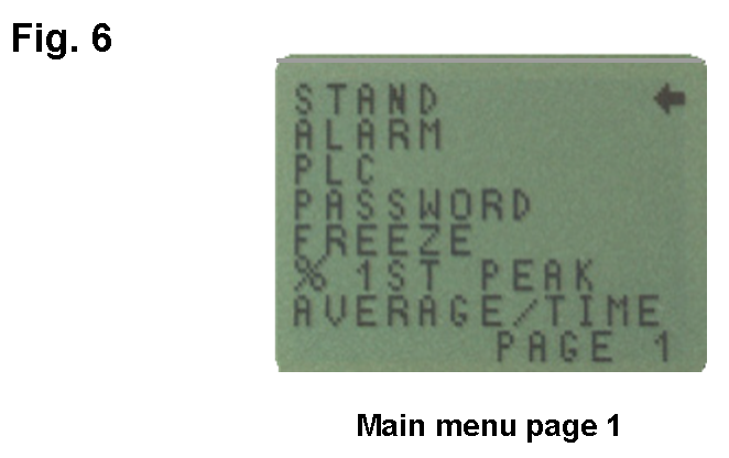
Press and hold the MENU key for approximately 3 seconds to access page 1 of the main-menu, (see Fig. 6). Pressing the MENU key again takes you to pages 2 and 3 of the main menu in turn. To move between the options listed on the 3 main-menu pages, press the UP and DOWN keys to move the cursor. Press the ENTER key to select sub-menus, activate features and enter values. Within sub-menus the UP and DOWN keys will also change numerical values. Press the ESC key to return to the relevant main-menu p
4.5.2 MAIN MENU PAGE 1
4.6 Stand
The AFG may be used to send a signal to control the Mecmesin range of motorised test stands via a dedicated cable.
To configure the signal output from the AFG, press and hold the MENU key until page 1 of the main menu appears. The cursor arrow will point to STAND. Press the ENTER key.
Contact your supplier for stand interface cable.
4.6.1 STAND sub-menu 1
The display will show:
STAND OFF/ON indicates status of stand control function.
REVERSE -Reverses the stand direction of travel at sample break (BREAK) or load-limit value (LIMIT). The test stand will reverse back to the start position as defined by the physical Microswitch.
STOP(BREAK) -Stops the stand at sample break or load-limit value (LIMIT). The test stand does not return to the start position.
CYCLE -Cycles a suitable test stand between load limits (UPPER, LOWER) for a set number of times (CYCLE). (The cycle function only refers to the VersaTest and MultiTest-d motorized test stands).
Select the desired function and press the ENTER key.
4.6.2 REVERSE sub-menu 1
Select UP or DOWN to tell the gauge which direction the stand will begin to move before the load-limit is reached. Press ENTER to select.
4.6.3 REVERSE sub-menu 2
The display will show:
BREAK -Sets the gauge to reverse at sample break. Press ENTER to select.
LIMIT -Sets the load-limit value to trigger the stand reverse function. Press ENTER to select.
4.6.4 BREAK sub-menu 1
Set % of loadcell capacity to indicate the value by which the load must fall to determine a break. Use a higher percentage for ‘noisy’ samples where the load may fluctuate before the sample finally breaks.
Set % BREAK using UP and DOWN keys and press the ENTER key to select and return to stand sub-menu 1.
4.6.5 LIMIT sub-menu 1
Set load-limit using UP and DOWN keys. (UNITS key changes the units of measurement for load-limit value). Press the ENTER key to select and return to stand sub-menu 1. Negative load-limits indicate compression
4.6.6 STOP sub-menu 2
The display will show:
BREAK -Sets the gauge to stop at sample break. Press ENTER to select.
LIMIT -Sets the load-limit value to trigger the stand stop function. Press ENTER to select.
4.6.7 Cycle
Select CYCLE using UP and DOWN keys and press the ENTER key to select.
4.6.8 Cycle sub-menu 1
Only used in conjunction with VersaTest and MultiTest-d motorised test stands.
The display will now show the UPPER load-limit, the LOWER load-limit and the number of CYCLES you wish to perform (range = 1 - 999). A diamond curser indicates which value is selected. Use the UP and DOWN keys to change the value, press and hold to scroll values. When the correct value is reached press the ENTER key to select.
When one of the stand control options (REVERSE, STOP or CYCLE) have been set press the ENTER key. The display will revert back to STAND sub-menu 1 and STAND ON will now be displayed. Press the ESC key to return to main-menu.
Note: It is recommended to press RESET key after each STAND operation.
Start the test by pushing the UP or DOWN switch on your test stand. The test stand will move to the UPPER load-limit and then travel back to the LOWER load-limit to perform the first cycle. Subsequent cycles will be performed and a cycle-counter is shown on the main display.
Note:
a) It is assumed that starting a test in the UP direction applies a tension force, and in the DOWN direction a compression force is applied.
b) The total number of cycles must be completed, e.g. if a sample breaks during the test, the AFG will try to continue applying load for the set number of cycles.
c) WARNING: At the end of your cycle test, the test sample could still be under load.
4.7 ALARM
The AFG has an audible and visual alarm feature which can be set to trigger on pass, fail or sample break criteria.
Up to 5 alarm settings may be stored, but only one setting may be used at any one time.
Alarms will not trigger in the first 1% of full-scale use.
4.7.1 ALARM sub-menu 1
4.7.1.1 (SETTING SELECTION)
To set an alarm, press and hold the MENU key until page 1 of the main-menu appears. The cursor arrow will point to ALARM. Press the ENTER key.
The display will show ALARM OFF, and 5 separate alarms, which may each be set up independently and stored by the user for easy access when changing test routines.
The cursor will be positioned against the current alarm in use, or against ALARM OFF if no alarm is selected.
4.7.2 ALARM sub-menu 2
4.7.2.1 (ALARM SET)
To activate an alarm, move the curser to the desired alarm and press ENTER.
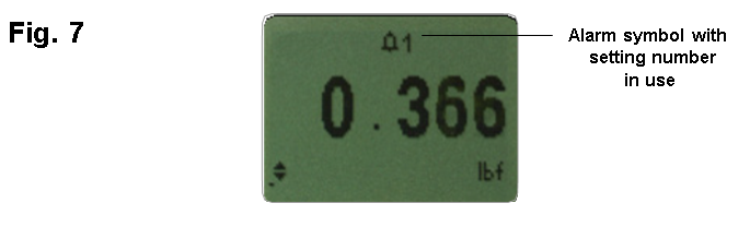
This will access the ALARM sub-menu 2, however this alarm has now been activated, and you can return to the main display by pressing the ESC key twice. The main display will now show an alarm ‘bell’ symbol accompanied by the number of the alarm selected, indicating that that alarm is activated (see Fig. 7).
If, however, you wish to change the settings of the selected alarm, choose SET by pressing the ENTER key in ALARM sub-menu 2.
4.7.3 ALARM sub-menu 3
4.7.3.1 (ALARM LIMITS)
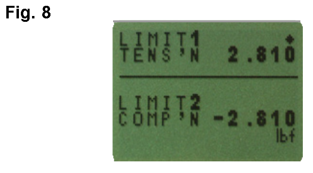
The display will now show the two limits - LIMIT 1 (lower limit) and LIMIT 2 (upper limit) - plus the value they are set to and whether they are in tension (TENS ’ N) or compression (COMP ’ N). A diamond cursor indicates which value is selected. Use the UP and DOWN keys to change the value, press and hold to scroll values. When the correct value is reached, press the ENTER key to set LIMIT 1. Repeat procedure for LIMIT 2 (see Fig. 8).
Note: The alarm limits are not active below 1% of the capacity of the tester.
4.7.4 ALARM sub-menu 4
4.7.4.1 (ALARM INDICATOR)
The display shows AUDIBLE, LED and BOTH with the arrow cursor indicating which feature is selected. This menu selects how the PASS/FAIL status of a value will be indicated.
AUDIBLE -Only the audible alarm will be activated when the value is a pass/fail.
LED -The PASS LED will illuminate green to indicate a pass status, the FAIL LED will illuminate orange or red to indicate low or high failures respectively.
BOTH -Both the LED and the audible alarm will be activated.
Use the UP and DOWN keys to move the cursor and press the ENTER key to select the desired feature.
4.7.5 ALARM sub-menu 5
4.7.5.1 (ALARM BAND)
The display shows OUT BAND and IN BAND. This menu selects which values are to be considered.
OUT BAND -Any value falling outside the set limits LIMIT 1 and LIMIT 2.
IN BAND -Any value falling between the set limits LIMIT 1 and LIMIT 2.
Use the UP and DOWN keys to move the cursor and press ENTER key to select the desired feature.
4.7.6 ALARM sub-menu 6
4.7.6.1 (ALARM PASS/FAIL)
The display shows PASS or FAIL. This menu sets the OUT BAND criteria.
PASS -Values, which fall either OUT BAND (or IN BAND, if selected), are a PASS and will cause an audible beep, illuminate an LED or both.
FAIL -Values, which fall either OUT BAND (or IN BAND, if selected), are a FAIL and will cause an audible beep, illuminate an LED or both.
Use UP and DOWN keys to move the cursor and press ENTER key to select the desired feature.
4.7.7 ALARM sub-menu 7
4.7.7.1 (ALARM BUZZER MODE)
The display shows BUZZER ON, CONTINUOUS and PULSE. This menu selects the length of time that the buzzer will sound, if AUDIBLE or BOTH has been selected in sub-menu 5.
CONTINUOUS -The buzzer sounds at a pre-set alarm value and stays on until the load falls below that pre-set.
PULSE -The buzzer pulses for a fixed time of one second every time the load crosses over each of the presets.
Use the UP and DOWN keys to move the cursor and press the ENTER key to select the desired feature.
The display will now return to the main menu, press ESC to return the main display.
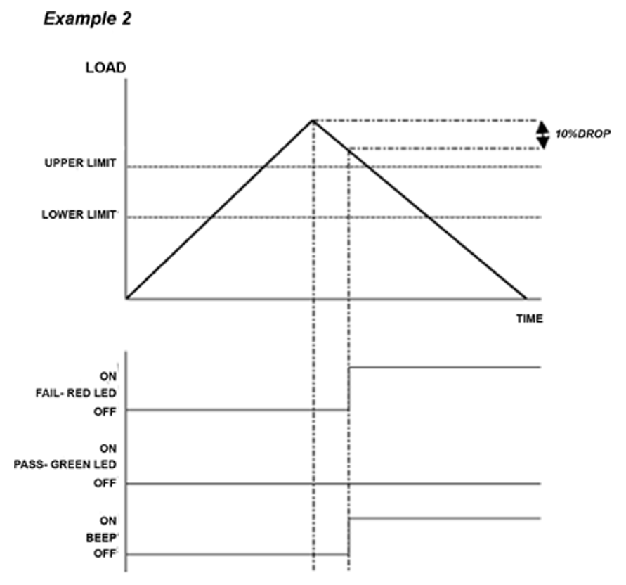
4.7.8 Alarm on break
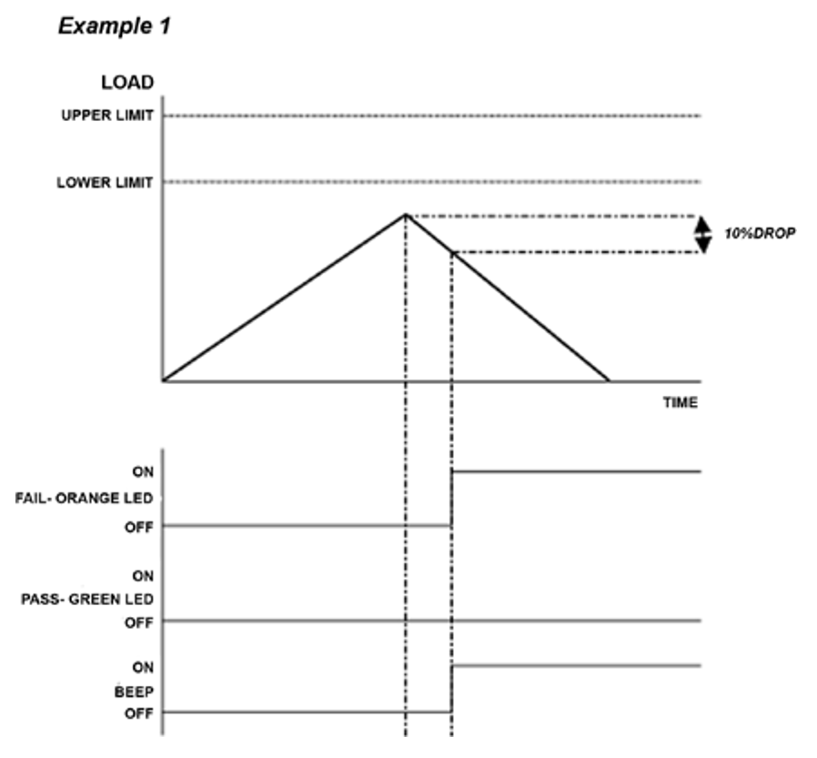
This feature is only activated when the % DROP feature is used in conjunction with the ALARM function. The AFG looks for a percentage (of full-scale) drop from peak load value, set in the % 1st PEAK menu (see page 23). The alarm can be used to indicate if the break point falls inside or outside the limits LIMIT 1 and LIMIT 2 set in the alarm menu - See examples 1 to 5 below.
4.7.9 Fast Selection of Alarms
In order to quickly and easily switch between pre-set alarms, it is possible to instantly access an ALARM SELECT page by holding down the RESET key for 3 seconds whilst in the main display.
The ALARM SELECT page is similar to the ALARM sub-menu 1- the display will show ALARM SELECT; OFF, and the 5 separate alarms.
The cursor will be positioned against the current alarm in use, or against ALARM OFF if no alarm is selected.
To activate an alarm, move the cursor to the desired alarm (or to OFF to deactivate alarms) and press ENTER. Alternatively, to cancel the command, press ESC.
The screen will return to the main display.
4.7.10 Example 1
Settings:
- BOTH LED and audio alarms are active -
- Alarm triggers on OUT BAND -
- Alarm is set to FAIL -
- % 1st PEAK is 10% of full-scale (e.g. AFG 100N must register drop of 10N) Main display is set to 1st peak tension screen
4.7.11 Example 2
Settings:
- BOTH LED and audio alarms are active
- Alarm triggers on OUT BAND
- Alarm is set to FAIL
- % 1st PEAK is 10% of full-scale (e.g. AFG 100N must register drop of 10N) Main display is set to 1st peak tension screen
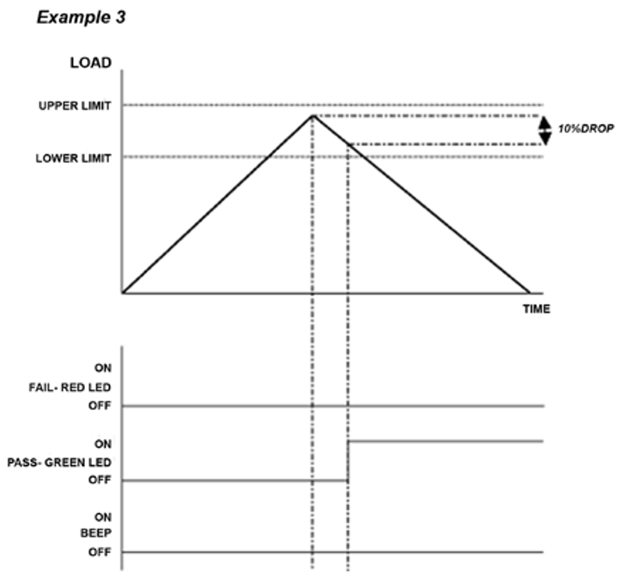
4.7.12 Example 3
Settings: -
- BOTH LED and audio alarms are active
- Alarm triggers on OUT BAND
- Alarm is set to FAIL
- % 1st PEAK is 10% of full-scale (e.g. AFG 100N must register drop of 10N) Main display is set to 1st peak tension screen
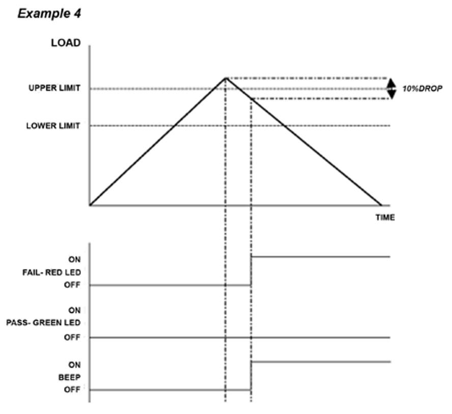
4.7.13 Example 4
Settings:
- BOTH LED and audio alarms are active
- Alarm triggers on OUT BAND
- Alarm is set to FAIL
- % 1st PEAK is 10% of full-scale (e.g. AFG 100N must register drop of 10N) Main display is set to 1st peak tension screen
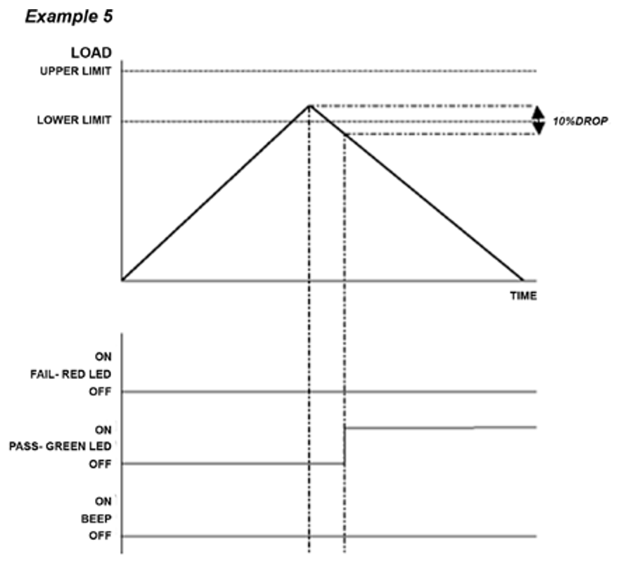
4.7.14 Example 5
Settings:
- BOTH LED and audio alarms are active
- Alarm triggers on OUT BAND
- Alarm is set to FAIL
- % 1st PEAK is 10% of full-scale (e.g. AFG 100N must register drop of 10N) Main display is set to 1st peak tension screen
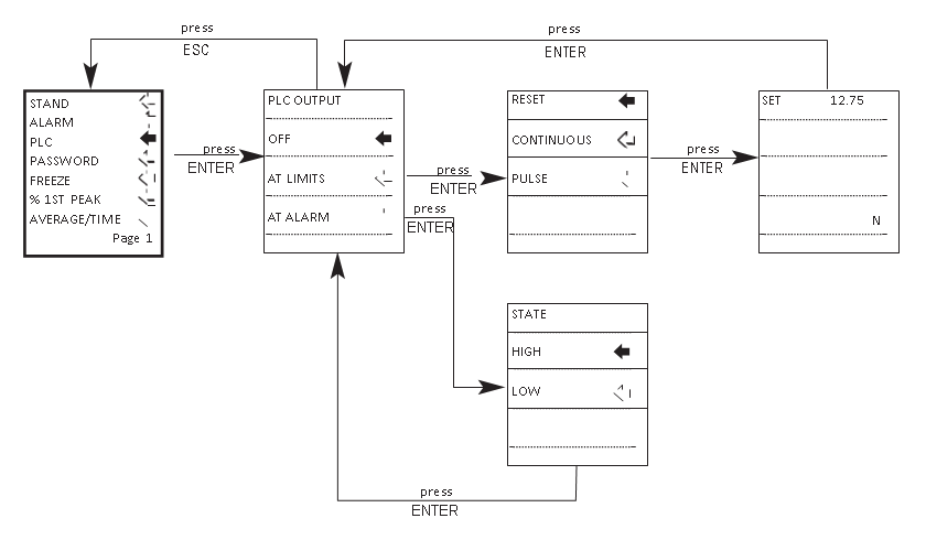
4.8 PLC
4.8.1 (Programmable Logic Controller)
For PLC applications, this function requires an external cable with a built-in solid-state relay - see Specifications on pages 54-56 for details of the signal.
To configure the signal output of the AFG, press and hold the MENU key until page 1 of the main menu appears. Press the DOWN key to move the arrow cursor to PLC and press ENTER.
4.8.2 PLC sub-menu 1
The display will show PLC OUTPUT:
OFF -Indicates PLC function status
AT LIMITS -Will set PLC signal at specified load limits
AT ALARM -Will tie in PLC signal with the AFG alarm settings
Select the desired function and press the ENTER key.
4.8.3 AT LIMITS sub-menu 1
The display will show:
RESET -When the load limit is reached, the output signal triggers and the RESET key must be pressed to clear the line before starting the next test.
CONTINUOUS -The output signal will be activated every time the load limit is reached and will remain on whilst the load exceeds the set limit.
PULSE -The output signal will be activated momentarily when the load limit is reached. The RESET key must be pressed before starting the next test.
Select the desired function and press the ENTER key.
4.8.4 AT LIMITS sub-menu 2
The display will show SET and a default load limit at which the output signal will trigger. To set the required load limit use UP and DOWN keys to adjust the value and the ENTER key to confirm the selection
4.8.5 AT ALARM sub-menu 1
The display will show STATE:
HIGH -Will set PLC signal high at AFG’s alarm.
LOW -Will set PLC signal low at AFG’s alarm.
Select the desired function and press the ENTER key.
The display will revert back to PLC sub-menu 1 and PLC ON will now be displayed.
Press ESC key to return to the main menu.
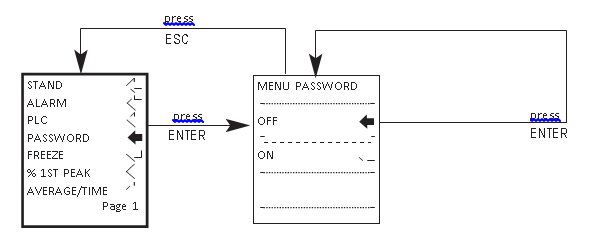
4.9 PASSWORD
Once the desired settings for the AFG have been established, it is possible to password protect the menu pages, so that no further changes may be made without authorised access.
To access the PASSWORD function, press and hold the MENU key until page 1 of the main-menu appears. Using the UP and DOWN keys, move the arrow cursor to PASSWORD, and press ENTER.
4.9.1 PASSWORD sub-menu 1
The display shows MENU PASSWORD:
OFF -Enables access to menu pages.
ON -Requires a password be entered to access the menu pages.
Use the UP and DOWN keys to move the arrow cursor against the desired selection and press ENTER, then press the ESC key twice to return to the main display
If the PASSWORD function has been enabled, and the MENU key is held down to access the menu pages from the main display, a screen showing 0000 will appear, and the menu password ‘6284’ must be entered to proceed. Use the UP and DOWN keys to select the first number, followed by ENTER to move on to the next number, and so on. If the password is entered incorrectly, the display will return to the main display.
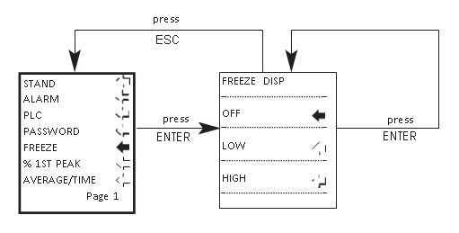
4.10 FREEZE
This feature is used to ‘freeze’ the main-display when an external signal is received. The AFG can be configured to freeze when going either low 1-0, falling edge (LO) or high 0-1, rising edge (HI). This is particularly useful for applications where an event occurs (e.g. switch testing). To clear the display press the RESET key.
To configure this function, press and hold the MENU key until main menu page 1 appears. Press the DOWN key to move the arrow cursor to FREEZE and press the ENTER key.
Use pins 7 & 10 for this function. When unconnected, pin 7 is pulled high internally.
4.10.1 FREEZE sub-menu 1
Select the setting desired LOW, HIGH or OFF for the FREEZE Display function using UP or DOWN arrow keys and press ENTER to select. Press ESC to return to the main menu page 1.
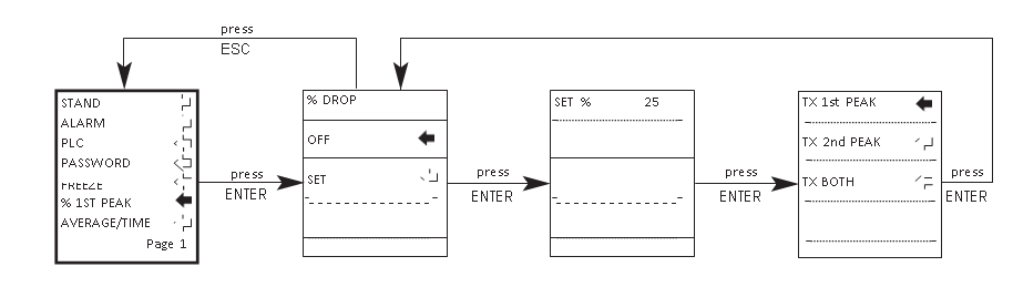
4.11 % 1st PEAK
When testing samples, the AFG enables the value at both the first peak and second peak to be measured and displayed. Once calculated, either result or both can be transmitted to a peripheral device (see Comms).
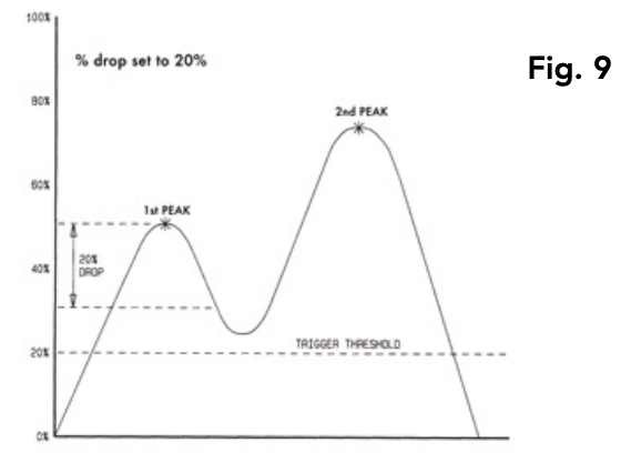
The % drop feature is based on the capacity of the AFG, and refers to the amount the 1st peak must drop before the software starts to look for the 2nd peak.
4.11.1 EXAMPLE
AFG 100N has % drop of 20 (=20N). If the peak load before sample break is 50N, the load must drop to 30N in order for the AFG to detect a 1st peak of 50N. If load continues to be applied above 50N (e.g. to 75N), the AFG will return 75N as the 2nd peak and 50N as the 1st peak. (see Fig. 9)
To enable the % 1st PEAK function, press and hold the MENU key until page 1 of the main menu appears. Press the DOWN key to move the cursor to % 1ST PEAK and press the ENTER key.
4.11.2 % 1st PEAK sub-menu 1
4.11.2.1 (SET)
The display will show % DROP OFF and SET. Press the ENTER key to change OFF to ON. Press the DOWN key to move the arrow cursor to SET and press the ENTER key.
4.11.3 % 1st PEAK sub-menu 2
4.11.3.1 (PERCENTAGE)
To determine what precisely is considered a break, you must define the % drop of full-scale value from the peak load observed prior to the break occurring. Use the UP and DOWN keys to set the percentage to the desired value and press the ENTER key. The % drop value selected also acts as a threshold, below which the % drop function will not be active.
4.11.4 % 1st PEAK sub-menu 3
4.11.4.1 (TX PEAKS)
The values which are to be transmitted to a peripheral device when using the TXD key on a dual max screen must now be selected. The following display will appear.
TX 1st PEAK -Sets the AFG to detect the force at which a sample breaks but is not necessarily the maximum force (e.g. detecting the force at which a tablet first begins to crack).
TX 2nd PEAK -Sets the AFG to transmit the 2nd peak only.
TX BOTH -Sets the AFG to transmit both the 1st peak and the 2nd peak.
Use the UP and DOWN keys to move the arrow cursor to the desired selection and press ENTER.
The display will return to the % 1st PEAK sub-menu 1. Press ESC to return to the main menu page 1, and again to return to the main display.
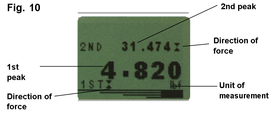
4.11.5 Max Modes with % 1st PEAK function enabled
When the % 1st PEAK function has been enabled, pressing the MAX key will scroll through the following max display modes, in order;
- 1st and 2nd tension peaks
- 1st tension peak only
- 1st and 2nd compression peaks (see Fig. 10)
- 1st compression peak only
- Current ‘live’ reading
Screen of 1st and 2nd peaks
When setting up the AFG, a graphical representation of the test provides a clear insight into the % drop factor required. Please contact Mecmesin or your approved supplier for details on Dataplot graphical charting software.
Example: AFG 100N has % drop of 20 (= 20N). If the peak load before sample break is 50N, the load must drop to 30N in order for the AFG to detect a 1st peak of 50N. If load continues to be applied above 50N (e.g. to 75N), the AFG will return 75N as MAX and 50N as 1st peak.
4.12 AV/TIME
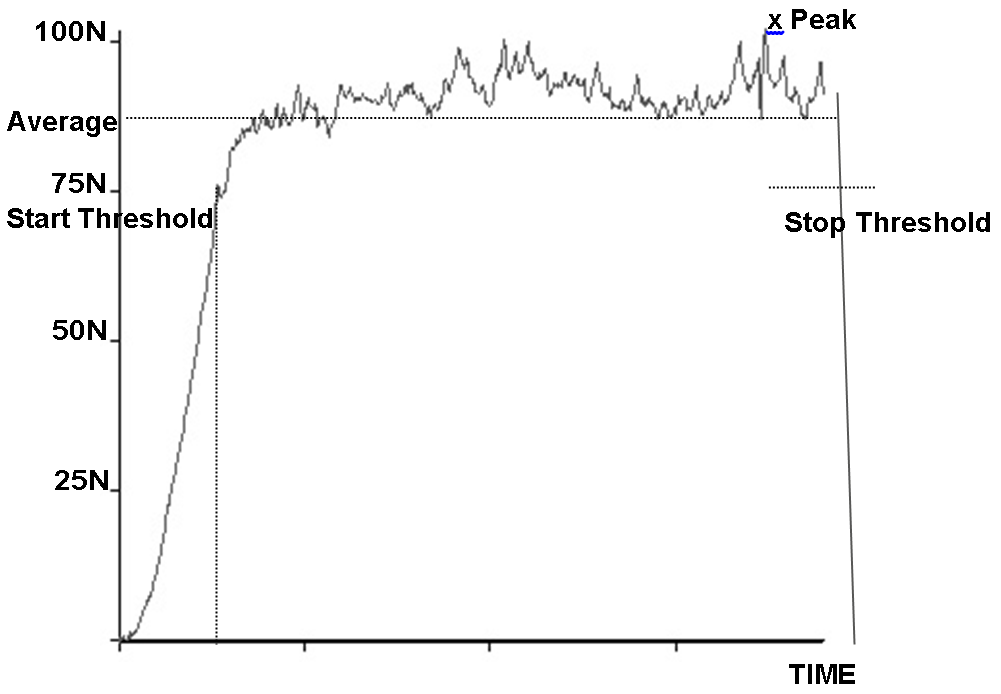
This function allows the average load reading to be displayed. The average starts being calculated when the START threshold (% of full-scale) is reached and stops being calculated when the load passes through the STOP threshold.
To set AVERAGE over TIME, press and hold the MENU key until page 1 of the main menu appears. Using the UP and DOWN keys, move the arrow cursor to AV/TIME and press ENTER.
The maximum duration of AV/ TIME calculation is approx. 22 minutes.
4.12.1 AV/TIME sub-menu 1
4.12.1.1 (SET)
The display will show AV/TIME OFF and SET. Press the ENTER key to change OFF to ON. Press the DOWN key to move the arrow cursor to SET and press the ENTER key.
4.12.2 AV/TIME sub-menu 2
4.12.2.1 (PERCENTAGE START/STOP)
The display will now show the START and STOP thresholds and the values to which they are set (as a % of full-scale).
Any load reading above the START threshold will be averaged over time. Averaging stops when the load reading passes through the STOP threshold.
A diamond cursor will indicate which value is selected.
Use the UP and DOWN keys to change the value, press and hold to scroll values. When the correct value is reached press the ENTER key to set START. Repeat procedure for setting STOP. The display will revert back to AV/TIME sub-menu 1.
To disable the AV/TIME function, press the ENTER key when the cursor arrow is aligned with ON in AV/TIME sub-menu 1. It will now display OFF.
Press the ESC key to return to the main menu page 1, and again to return to the main display.
The maximum duration of AV/TIME calculation is approx. 22 minutes. When the time limit expires, ‘AT’ is displayed in the main display, and the MAX key must be pressed in order to clear ‘AT’ and continue use of the AFG
4.12.3 MAIN MENU PAGE 2
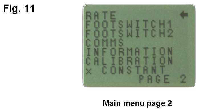
4.13 Rate
This function allows the selection of the gauge data capture rate, i.e. the amount of averaging performed by the internal electronics before the load reading is displayed. Data are sampled at 5000Hz and averaged to 2 levels.
MEDIUM -80Hz (Default)
HIGH -2000Hz
4.13.1 RATE sub-menu 1
To set RATE, press and hold the MENU key until the main menu page 1 appears. Press and release the MENU key to access the main menu page 2. Using the UP and DOWN keys move the arrow cursor to RATE, and press ENTER.
Using the UP and DOWN keys select the relevant level (MEDIUM or HIGH) and press the ENTER key.
Press the ESC key to return to the main menu page 2, and again to return to the main display.
4.14 FOOTSWITCH 1
The AFG has two footswitch input pins on the 15-way D connector. This allows the footswitch to be assigned to replicate one of each of the five main key functions, MAX, UNITS, TXD, ZERO and RESET.
This feature is useful when integrating the AFG into test or production systems.
Note: A footswitch assigned to the UNITS key can allow entry into the menu page, but the gauge will not respond to further footswitch operations from either footswitch 1 or 2 once in the menu.
4.14.1 FOOTSWITCH 1
4.14.1.1 sub-menu 1
To assign the function of a key to FOOTSWITCH 1, press and hold the MENU key until page 1 of the mainmenu appears. Press and release the MENU key to access the main menu page 2. Using the UP and DOWN keys, move the arrow cursor to FOOTSWITCH 1 and press ENTER.
Using the UP and DOWN keys, select the relevant key (MAX, UNITS, TXD, ZERO or RESET) then press the ENTER key, or to cancel this option, select OFF and press the ENTER key.
Press the ESC key to return to page 2 of the main-menu, and again to return to the main display.
4.15 FOOTSWITCH 2
To assign the function of a key to FOOTSWITCH 2, press and hold the MENU key until page 1 of the mainmenu appears. Press and release the MENU key to access the main menu page 2. Using the UP and DOWN keys move the arrow cursor to FOOTSWITCH 2, and press ENTER.
4.15.1 FOOTSWITCH 2
4.15.1.1 sub-menu 1
Using the UP and DOWN keys, select the relevant key (MAX, UNITS, TXD, ZERO or RESET) and press the ENTER key, or to cancel this option, select OFF and press the ENTER key.
Press the ESC key to return to page 2 of the main-menu, and again to return to the main display.
Note: Footswitch 2 is multiplexed with the Smart Sensor analogue voltage out. If a ‘Smart’ Sensor is attached, Footswitch 2 functions are disabled.
4.16 COMMS
Communications settings are selected to configure interfacing of the AFG with peripheral devices. The menu is also used to configure the storage settings of the AFG, which may store up to 500 readings in its on-board memory
To access the COMMS settings, press and hold the MENU key until page 1 of the main menu appears. Press and release the MENU to access page 2 of the main menu, use the DOWN key to move the arrow cursor to COMMS and press ENTER.
4.16.1 COMMS sub-menu 1
The display shows:
PORT -Communicates with peripheral device. Transmission of the displayed load reading can be set to include unit of measurement (UNITS ON or OFF), and BAUD rate can also be set.
STORE MEM -Stores a single load reading to the internal memory. With this option selected, pressing the TXD key when in the max modes of the main display will send the displayed value to memory. Up to 500 readings may be stored in the memory.
SEND MEM -Sends all load readings stored in the internal memory to a peripheral device (e.g PC or data logger).
CLEAR MEM -Erases all load readings stored in memory.
Using UP and DOWN keys select the relevant option. When setting PORT, you will access PORT sub-menu 1.
4.16.2 PORT sub-menu 1
4.16.2.1 (TX UNITS)
Transmission of the displayed load reading can be set to include the unit of measurement, the display shows TX UNITS OFF or ON.
Use the UP or DOWN key to position the arrow cursor against the desired selection and press the ENTER key.
4.16.3 PORT sub-menu 2
4.16.3.1 (TX SIGN)
The display will show TX SIGN OFF and ON. This will transmit a negative sign for compression readings if set to ON. Use the UP or DOWN key to position the arrow cursor against the desired selection and press the ENTER key.
4.16.4 PORT sub-menu 3
4.16.4.1 (BAUD RATE)
The transmission (or Baud) rate can now be set. Use the UP or DOWN key to position the arrow cursor at the relevant speed (9600, 19200, 57600 or 115200).
Press ENTER to select.
4.16.5 PORT sub-menu 4
4.16.5.1 (TERMINAL)
Additional characters can be appended to the transmitted load (RS232 only). These can be set to NULL (nothing), CR (carriage return), LF (line feed) or CR LF. Use the UP or DOWN key to position the arrow cursor at the desired setting.
Press ENTER to select.
4.16.6 PORT sub-menu 5
4.16.6.1 (LINE DELAY)
If required, a LINE DELAY, to be executed after each reading is sent, can now be set.
Use the UP or DOWN key to set this value from 0 to 5 seconds in one-second intervals.
Press ENTER to select.
4.16.7 PORT sub-menu 6
4.16.7.1 (TX THRESHOLD)
For use with continuous readings only, a % threshold for the start of transmission can now be set.
Use the UP or DOWN key to set this value from 0% to 100%
Press ENTER to select.
4.16.8 PORT sub-menu 7
4.16.8.1 (TX METHOD)
Method of transmission, RS232, DIGIMATIC or DUAL (both), can now be set.
Use the UP or DOWN key to position the arrow cursor at the desired setting.
Press ENTER to select.
The display will return to the COMMS sub-menu 1.
4.16.9 COMMS sub-menu 1
4.16.9.1 (further options)
4.16.9.2 STORE TO MEMORY
To set STORE MEM, move the arrow cursor against it in COMMS sub-menu 1 and press the ENTER key.
This will cause a memory counter to appear in the main display, that is incremented each time a reading is stored, by pressing the TXD key.
Note: The CYCLE counter and memory counter cannot appear on the main display simultaneously. If both
are selected, the cycle counter is displayed. When pressing TXD to store a reading, the memory counter is displayed momentarily to show the number of readings stored.
You will now return to COMMS sub-menu 1.
4.16.9.3 SEND FROM MEMORY
To set SEND MEM, move the arrow cursor against it in COMMS sub-menu 1 and press the ENTER key. This will cause a TX symbol to flash in the main display as the memory data is now transmitted to a peripheral device. The data is transmitted at the settings defined by PORT. After transmission of data you will now return to COMMSsub-menu 1.
4.16.9.4 CLEAR THE MEMORY
To set CLEAR MEM, move the arrow cursor against it in COMMS sub-menu 1 and press the ENTER key.
This now erases all the data stored in the memory. The memory counter is now reset to zero. After clearing the memory you will now return to COMMS sub-menu 1.
Press the ESC key to return to page 2 of the main-menu, and again to return to the main display.
4.17 INFORMATION
Displays calibration information.
![]() Tension span
Tension span
![]() Compression span
Compression span
I Initial Zero
G Gravitational constant
Z Current zero
This is for information only and may be required for diagnostic purposes by your distributor.
4.18 Calibration
If you suspect that your AFG has sustained an overload, it is possible to check the status of the AFG immediately.
Symptoms of overload may be (a) OL in display (b) buzzer sound (c) load indicator bar present even under zero load.
An instrument showing an overload condition cannot be relied upon to provide accurate, repeatable measurement - consult your supplier.
Place the AFG (or your external SMART sensor) on a flat level surface. Press and hold the MENU key until page 1 of the main-menu appears. Press and release the MENU key to access the main menu page 2. Using the UP and DOWN keys move the arrow cursor to CALIBRATION, and press ENTER.
4.18.1 CALIBRATION sub-menu 1
The display will show 0000. Press the ENTER key four times (to enter 0000 as the password).
4.18.2 CALIBRATION sub-menu 2
CALIBRATION sub-menu 2 (the sensor diagnostic test screen) will appear on the display, as shown in Fig. 12.
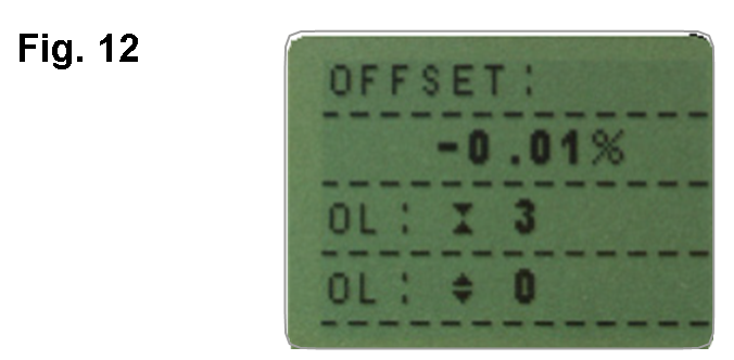
The offset value provides an indication of the condition of the loadcell, and is defined as the % difference between the initial zero and the current zero reading.
If the offset is between 5 - 10 %, please contact your supplier to arrange a re-calibration of your AFG.
If the offset is greater than 10 %, please contact your supplier to arrange for a possible sensor replacement.
These values are given as an indicator only - the need for calibration/repair may vary according to the individual characteristics of the sensor.
In addition to the offset, the number of overloads (OL) experienced by the loadcell in both compression and tension directions are displayed. An overload is registered when a load exceeding 150% of the rated capacity of the loadcell is applied in either direction.
Press the ESC key to return to the main menu page 2, and again to return to the main display.
4.19 x CONSTANT
A constant multiplier from 0.001 to 10.000 can be set for a selectable base unit. Units will be replaced with an X on the main display and the UNITS key will have no effect on the displayed units.
To set x CONSTANT press and hold the MENU key until page 1 of the main-menu appears. Press and releasethe MENU key to access the main menu page 2. Using the UP and DOWN keys move the arrow cursor to x CONSTANT, and press ENTER.
4.19.1 x CONSTANT sub-menu 1
The display will show X CONST OFF and SET.
Press ENTER key to change X CONST OFF to X CONST ON.
Press the DOWN key to move the arrow curser to SET and press the ENTER key.
4.19.2 x CONSTANT sub-menu 2
Using the UP and DOWN keys set theX CONSTANT multiplier to the desired value. The unit this will apply to is shown in the lower right corner of the screen and can be adjusted with the UNITS key.
Press the ESC key to return to main menu page 2 and press the ESC key again to return to the main display.
4.19.3 MAIN MENU PAGE 3
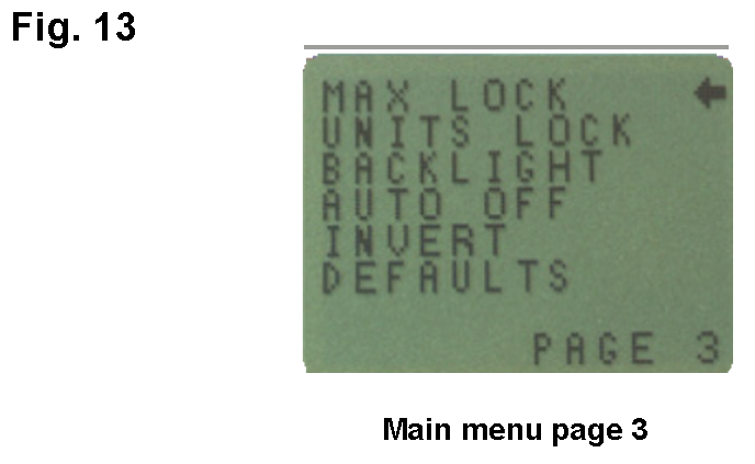
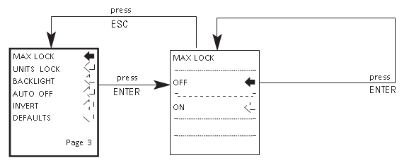
4.20 MAX LOCK
Once the desired Max display mode has been selected, it is possible to lock the mode, so that further pressing the MAX key results in no change.
To access the MAX LOCK function, press and hold the MENU key until page 1 of the main-menu appears. Press and release the MENU key twice to access the main menu page 3. Using the UP and DOWN keys, move the arrow cursor to MAX LOCK, and press ENTER.
4.20.1 MAX LOCK sub-menu 1
The display shows MAX LOCK:
OFF - Unlocks the max display mode.
ON - Locks the current max display mode.
Use the UP and DOWN keys to move the arrow cursor against the desired selection and press ENTER.
The display will return to the main menu page 3, press the ESC key to return to the main display.
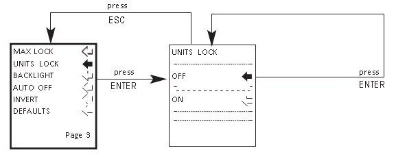
4.21 UNITS LOCK
4.21.1 UNITS LOCK sub-menu 1
Once the desired unit of measurement has been selected, it is possible to lock the units, so that further pressing the UNITS key results in no change.
To access the UNITS LOCK function, press and hold the MENU key until page 1 of the main-menu appears. Press and release the MENU key twice to access the main menu page 3. Using the UP and DOWN keys, move the arrow cursor to UNITS LOCK, and press ENTER.
The display shows UNITS LOCK:
OFF - Unlocks the units.
ON - Locks the units to the current setting.
Use the UP and DOWN keys to move the arrow cursor against the desired selection and press ENTER.
The display will return to the main menu page 3, press the ESC key to return to the main display.
Note: The UNITS/MENU key can still be used to enter the menu pages when the UNITS LOCK function is enabled.
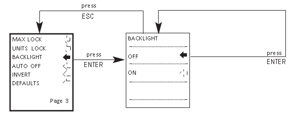
4.22 BACKLIGHT
It is possible to activate a backlight on the AFG display.
To access the BACKLIGHT function, press and hold the MENU key until page 1 of the main-menu appears. Press and release the MENU key twice to access the main menu page 3. Using the UP and DOWN keys, move the arrow cursor to BACKLIGHT, and press ENTER.
4.22.1 BACKLIGHT sub-menu 1
The display shows BACKLIGHT OFF and ON:
Use the UP and DOWN keys to move the arrow cursor against the desired selection and press ENTER.
The display will return to the main menu page 3, press the ESC key to return to the main display.
When activated, the backlight will remain on for 30 seconds since the last key press or last load applied registering over 2% of full scale.
Note: Battery consumption is doubled when using the backlight.
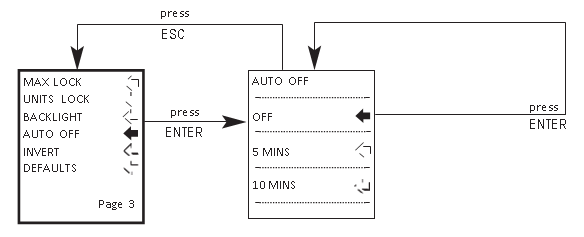
4.23 AUTO OFF
To conserve battery power, it is possible to activate an auto-off function so that the AFG powers down 5 or 10 minutes after either the last key press, or the last load applied greater than 2% of full scale.
To access the AUTO OFF function, press and hold the MENU key until page 1 of the main-menu appears. Press and release the MENU key twice to access the main menu page 3. Using the UP and DOWN keys, move the arrow cursor to AUTO OFF, and press ENTER.
4.23.1 AUTO OFF sub-menu 1
The display shows AUTO OFF:
OFF - Disables auto-off function.
5 MINUTES - AFG will automatically power down after 5 mins.
10 MINUTES - AFG will automatically power down after 10 mins.
Use the UP and DOWN keys to move the arrow cursor against the desired selection and press ENTER.
The display will return to the main menu page 3, press the ESC key to return to the main display.
Note: The AUTO OFF function is disabled whilst accessing the menu pages, regardless of setting.
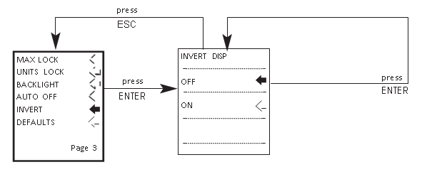
4.24 INVERT
For hand-held tension applications it is often desirable to reverse the display, so the operator can read it more comfortably.
To access the INVERT function, press and hold the MENU key until page 1 of the main-menu appears. Press and release the MENU key twice to access the main menu page 3. Using the UP and DOWN keys, move the arrow cursor to INVERT, and press ENTER.
Note: The menu pages are not inverted when the INVERT function is enabled.
4.24.1 INVERT sub-menu 1
The display shows INVERT OFF and ON:
Use the UP and DOWN keys to move the arrow cursor against the desired selection and press ENTER.
The display will return to the main menu page 3, press the ESC key to return to the main display.
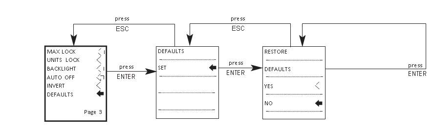
4.25 DEFAULTS
To restore the factory default settings of your AFG, press and hold the MENU key until page 1 of the main- menu appears. Press and release the MENU key twice to access the main menu page 3. Using the UP and DOWN keys, move the arrow cursor to DEFAULTS, and press ENTER.
4.25.1 DEFAULTS sub-menu 1
The display shows DEFAULTS SET, press the ENTER key.
4.25.2 DEFAULTS sub-menu 2
The display shows RESTORE DEFAULTS YES and NO. Align the arrow cursor with YES to restore default settings, or with NO to cancel the action, and press the ENTER key.
The display will return to the main menu page 3, press the ESC key to return to the main display.
4.25.3 Factory Default Settings
|
Menu Function |
Default Setting |
|
STAND |
OFF |
|
ALARM |
OFF |
|
PLC |
OFF |
|
PASSWORD |
OFF |
|
FREEZE |
OFF |
|
% 1st PEAK |
OFF |
|
AV TIME |
OFF |
|
RATE |
MEDIUM |
|
FOOTSWITCH1 |
OFF |
|
FOOTSWITCH2 |
OFF |
|
COMMS |
|
|
PORT |
SELECTED |
|
UNITS |
OFF |
|
SIGN |
ON |
|
BAUD |
9600 |
|
TERMINAL |
CR AND LF |
|
LINE DELAY |
0 SECONDS |
|
TX THRESHOLD |
2% |
|
TX METHOD |
RS232 |
|
x CONSTANT |
OFF |
|
MAX LOCK |
OFF |
|
UNITS LOCK |
OFF |
|
BACKLIGHT |
OFF |
|
AUTO OFF |
OFF |
|
INVERT |
OFF |
4.26 RS232 Commands Table: Configuration
It is possible to remotely read/configure the settings of your AFG by sending the following RS232 command characters:
|
Character in ASCII |
Decimal |
Hexadecimal |
Function |
|
|
M |
77 |
0x4D |
Current mode |
|
|
U |
85 |
0x55 |
Current units |
|
|
C |
67 |
0x43 |
Loadcell capacity |
|
|
@ |
64 |
0x40 |
Configuration status request |
|
|
* |
42 |
0x2A |
Continuous transmit |
|
|
r |
114 |
0x72 |
Normal screen |
|
|
s |
115 |
0x73 |
Dual Max* |
|
|
t |
116 |
0x74 |
Max Tension ( or Clockwise)* |
|
|
u |
117 |
0x75 |
Max Compression (or Counter-clockwise)* |
|
|
v |
118 |
0x76 |
Dual Peak Tension (or Clockwise)** |
|
|
w |
119 |
0x77 |
1st Peak Tension (or Clockwise)** |
|
|
x |
120 |
0x78 |
Dual Peak Compression (or Counter- clockwise)** |
|
|
y |
121 |
0x79 |
1st Peak Compression (or Counter- clockwise)** |
|
|
a |
97 |
0x61 |
mN |
N.m |
|
b |
98 |
0x62 |
N |
N.cm |
|
c |
99 |
0x63 |
kN |
mN.m |
|
d |
100 |
0x64 |
gf |
gf.cm |
|
e |
101 |
0x65 |
kgf |
kgf.cm |
|
f |
102 |
0x66 |
ozf |
kgf.m |
|
g |
103 |
0x67 |
lbf |
ozf.in |
|
h |
104 |
0x68 |
- |
lbf.ft |
|
i |
105 |
0x69 |
- |
lbf.in |
|
? |
63 |
0x3F |
Transmit the current reading |
|
|
CTRL a |
1 |
0x01 |
TXD key |
|
|
CTRL b |
2 |
0x02 |
UNITS key |
|
|
CTRL c |
3 |
0x03 |
MAX key |
|
|
CTRL d |
4 |
0x04 |
RESET key |
|
|
CTRL e |
5 |
0x05 |
ZERO key |
|
Note: Displayed units will only change if it is applicable to the loadcell capacity of the gauge.
*Only if % 1st Peak function is disabled
**Only if % 1st Peak function is enabled
4.27 RS232 Command Responses: Information
It is possible to remotely interrogate your AFG by sending the following RS232 commands. This will inform you which settings are currently configured.
4.27.1 Command: M
|
Response |
AFG Display Mode |
|
Normal |
Normal Mode |
|
MaxC |
Max Compression (or Counter-clockwise) |
|
MaxT |
Max Tension (or Clockwise) |
|
MaxDual |
Dual Max Screen |
|
1stC |
1st Peak Compression (or Counter-clockwise) |
|
1stC Dual |
Dual 1st Compression Screen (or Counter-clockwise) |
|
1stT |
1st Peak Tension (or Clockwise) |
|
1stT Dual |
Dual 1st Tension Screen (or Clockwise) |
4.27.2 Command: U
|
Response for Force Loadcell |
Response for Torque Loadcell |
|
N |
N.m |
|
mN |
N.cm |
|
kN |
mN.m |
|
gf |
gf.cm |
|
kgf |
kgf.cm |
|
ozf |
kgf.m |
|
lbf |
lbf.ft |
|
lbf.in |
|
|
ozf.in |
4.27.3 Command: C
The loadcell size in N (or N.m for torque).
Note: ‘xxxx’ will be transmitted if the loadcell is not calibrated, or has a serious fault. Contact Mecmesin or your supplier.
4.27.4 Command: @
When all options are OFF, and the AFG is set at defaults, you will receive the following information listing:
|
RESPONSE |
EXPLANATION OF RESPONSE |
|
AFG |
Gauge type |
|
10.000 |
Loadcell size in N as per transmitting ‘C’ |
|
V01 |
Version number |
|
Normal |
Mode of operation as per transmitting ‘M’ |
|
N |
Units of operation as per transmitting ‘U’ |
|
Menu Function |
Default Setting |
|
STAND |
OFF |
|
ALARM |
OFF |
|
PLC |
OFF |
|
PASSWORD |
OFF |
|
FREEZE |
OFF |
|
% 1ST PEAK |
OFF |
|
AV TIME |
OFF |
|
RATE |
MED |
|
FOOTSWITCH1 |
OFF |
|
FOOTSWITCH2 |
OFF |
|
COMMS |
P,OFF,ON,9600,CL,0,2,S |
|
x CONSTANT |
OFF |
|
MAX LOCK |
OFF |
|
UNITS LOCK |
OFF |
|
BACKLIGHT |
OFF |
|
AUTO OFF |
OFF |
|
INVERT |
OFF |
When all options are ON, you will receive the following information listing for each option:
4.27.5 STAND ON options
|
STAND ON, R, 1, 2, 3 |
|
|
R |
Reverse |
|
1 |
U = Up, D = Down |
|
2 |
B = Break, L = Limit |
|
3 |
Break percent or Limit Value |
|
STAND ON, S, 1, 2 |
|
|
S |
Stop |
|
1 |
B = Break, L = Limit |
|
2 |
Break percent or Limit Value |
|
STAND ON, C, 1, 2, 3 |
|
|
C |
Cycle |
|
1 |
Upper cycle value |
|
2 |
Lower cycle value |
|
3 |
Cycles |
4.27.6 ALARM ON options
|
ALARM ON, 1, 2, 3, 4, 5, 6, 7 |
|
|
1 |
Alarm Number Selected; 1, 2, 3, 4 or 5 |
|
2 |
x Limit1 value |
|
3 |
x Limit2 value |
|
4 |
B = Buzzer, L = LED, BL = Buzzer & LED |
|
5 |
O = Out of Band, I = In Band |
|
6 |
P=Pass, F=Fail |
|
7 |
C = Continuous, P = Pulse, or blank |
4.27.7 PLC OUTPUT ON options
|
PLC OUTPUT ON, L, 1, 2 |
|
|
L |
At limits |
|
1 |
R = Reset, C = Continuous, P = Pulse |
|
2 |
Limit value |
|
PLC OUTPUT ON, A, 1 |
|
|
A |
At alarm |
|
1 |
H = High, L = Low |
4.27.8 PASSWORD 1 options
|
PASSWORD 1 |
|
|
1 |
Menu Password ON or OFF |
4.27.9 FREEZE ON options
|
FREEZE ON, 1 |
|
|
1 |
L = Low, H = High |
4.27.10 % 1st Peak options
|
% 1st Peak ON,1,2 |
|
|
1 |
Drop in percent |
|
2 |
Load Transmitted, 1st for 1st peak, 2nd for 2nd peak, 1st&2nd for both |
4.27.11 AV TIME ON options
|
AV TIME ON, 1, 2 |
|
|
1 |
Start Threshold value |
|
2 |
Stop Threshold value |
4.27.12 RATE 1 ON options
|
RATE 1 |
|
|
1 |
M = Medium, H = High |
4.27.13 FOOTSWITCH1 ON options
|
FOOTSWITCH1 ON, 1 |
|
|
1 |
Footswitch 1 - M = Max, U = Units, T = Txd, Z = Zero, R = Reset |
4.27.14 FOOTSWITCH2 ON options
|
FOOTSWITCH2 ON, 1 |
|
|
1 |
Footswitch 2 - M = Max, U = Units, T = Txd, Z = Zero, R = Reset |
4.27.15 COMMS settings
|
COMMS 1, 2, 3, 4, 5, 6, 7, 8 |
|
|
1 |
P = Port, M = Store in memory |
|
2 |
Units being transmitted, ON or OFF |
|
3 |
Sign being transmitted, ON or OFF |
|
4 |
Baud rate value |
|
5 |
C = Carriage return, L = Line feed, CL = both |
|
6 |
Line delay in seconds |
|
7 |
Constant transmit threshold in percent |
|
8 |
S = Serial RS232, D = Digimatic, B = Both |
4.27.16 X CONST ON options
|
X CONST 1 |
|
|
1 |
X CONST value with units |
4.27.17 MAX LOCK 1 options
|
MAX LOCK 1 |
|
|
1 |
Max key locked, ON or OFF |
4.27.18 UNIT LOCK 1 options
|
UNITS LOCK 1 |
|
|
1 |
Units key locked, ON or OFF |
4.27.19 BACKLIGHT 1 options
|
BACKLIGHT 1 |
|
|
1 |
Backlight enabled, ON or OFF |
4.27.20 AUTO-OFF 1 options
|
AUTO-OFF 1 |
|
|
1 |
Auto-off time, OFF, 5 mins or 10 mins |
4.27.21 INVERT 1 options
|
INVERT 1 |
|
|
1 |
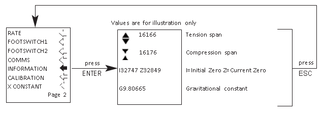
Display inverted, ON or OFF |
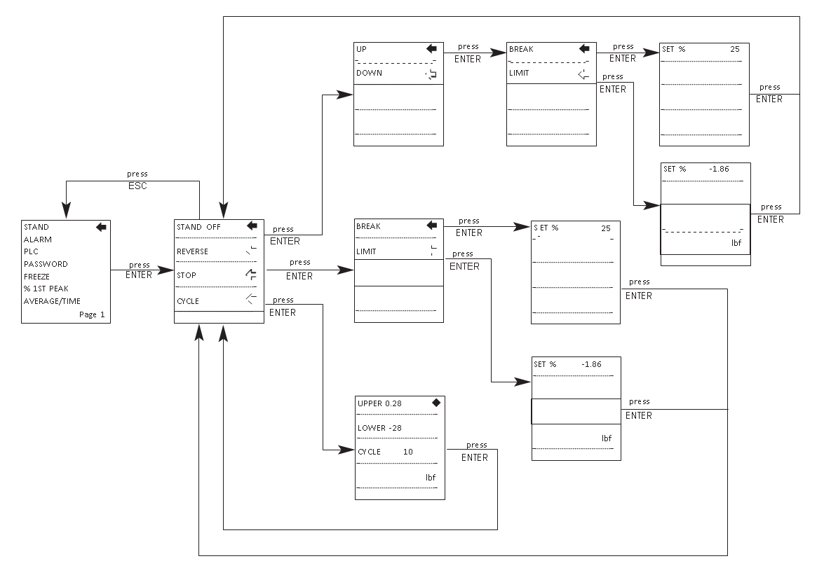
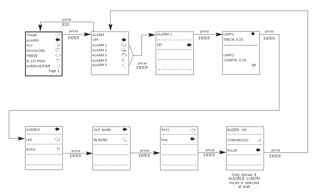
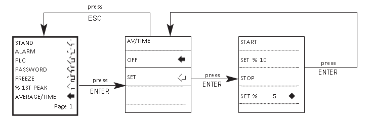
4.28 Advanced Menu Options Flow Chart Menu Page 1
On the following pages are flowcharts to help you navigate the menus found in the AFG. They appear in the order they appear on the three pages of the main menu on the instrument.
4.28.1 STAND
4.28.2 ALARM
4.28.3 PLC
4.28.4 PASSWORD
4.28.5 FREEZE
4.28.6 % 1ST PEAK
4.28.7 AVERAGE/TIME
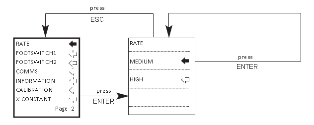
4.29 Advanced Menu Options Flow Chart Menu Page 2
4.29.1 RATE
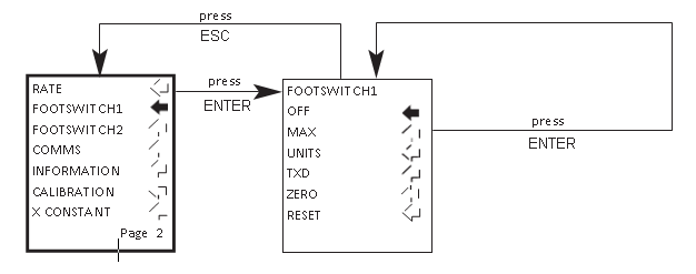
4.29.2 FOOTSWITCH1
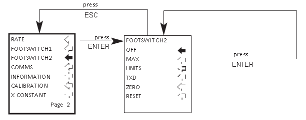
4.29.3 FOOTSWITCH2
4.29.4 COMMS
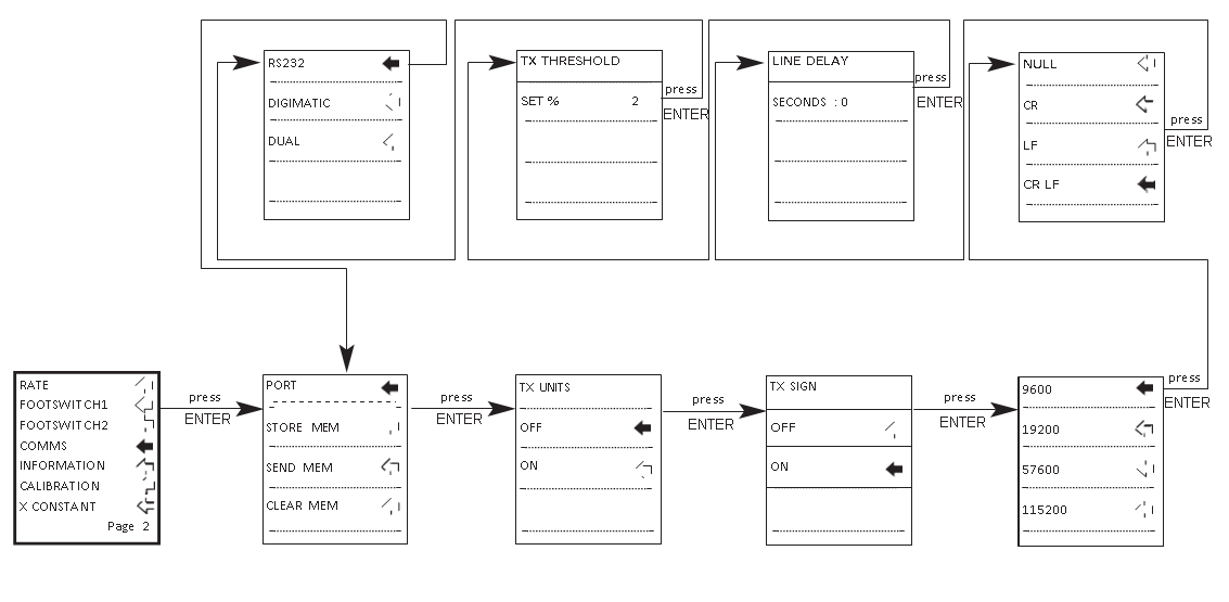
4.29.5 INFORMATION
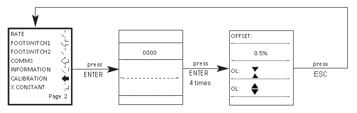
4.29.6 CALIBRATION
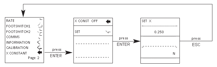
4.29.7 X CONSTANT
4.30 Advanced Menu Options Flow Chart Menu Page 3
4.30.1 MAX LOCK
4.30.2 UNITS LOCK
4.30.3 BACKLIGHT
4.30.4 AUTO OFF
4.30.5 INVERT
4.30.6 DEFAULTS
4.31 DIMENSIONS
4.31.1 Front view
4.31.2 Rear view
4.31.3 Side view
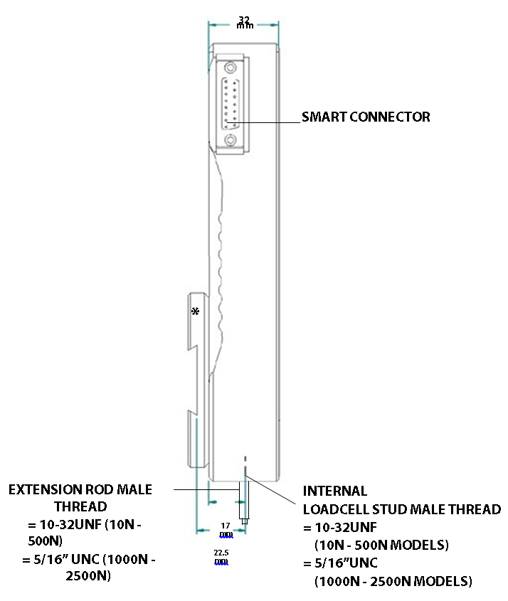
* Shown with Dovetail Mounting Bracket (supplied with Mecmesin Test Stands)
4.32 AFG SPECIFICATIONS
4.32.1 Range & Resolution Accuracy
|
Model no: |
mN |
N |
kN |
gf |
kgf |
ozf |
lbf |
|
AFG 2.5 |
2,500 x 0.5 |
2.5 x 0.0005 |
- |
250 x 0.05 |
- |
9 x 0.002 |
0.55 x 0.0001 |
|
AFG 5 |
5,000 x 1 |
5 x 0.001 |
- |
500 x 0.1 |
0.5 x 0.0001 |
18 x 0.005 |
1.1 x 0.0002 |
|
AFG 10 |
10,000 x 2 |
10 x 0.002 |
- |
1,000 x 0.2 |
1 x 0.0002 |
35 x 0.01 |
2.2 x 0.0005 |
|
AFG 25 |
25,000 x 5 |
25 x 0.005 |
- |
2,500 x 0.5 |
2.5 x 0.0005 |
90 x 0.02 |
5.5 x 0.001 |
|
AFG 50 |
50,000 x 10 |
50 x 0.01 |
- |
5,000 x 1 |
5 x 0.001 |
180 x 0.05 |
11 x 0.002 |
|
AFG 100 |
- |
100 x 0.02 |
- |
10,000 x 2 |
10 x 0.002 |
350 x 0.1 |
22 x 0.005 |
|
AFG 250 |
- |
250 x 0.05 |
- |
25,000 x 5 |
25 x 0.005 |
900 x 0.2 |
55 x 0.01 |
|
AFG 500 |
- |
500 x 0.1 |
- |
50,000 x 10 |
50 x 0.01 |
1,800 x 5 |
110 x 0.02 |
|
AFG 1000 |
- |
1,000 x 0.2 |
1 x 0.0002 |
- |
100 x 0.02 |
3,500 x 1 |
220 x 0.05 |
|
AFG 2500 |
- |
2,500 x 0.5 |
2.5 x 0.0005 |
- |
250 x 0.05 |
9,000 x 2 |
550 x 0.1 |
±0.1% of full-scale
Calibration temperature: 20°C ±2°C Operating temperature: 10°C - 35°C
Temperature shift at zero load: ±0.01% of full-scale/°C
4.32.2 Output
RS232-C: 8 data bits, 1 Start bit, 1 Stop bit, no parity Digimatic (BCD) Output:
Analogue: Approx. ±2-5V uncalibrated for full scale tension/ compression (or clockwise/counter-clockwise)
If calibrated:
0 to +4V full scale for tension (or clockwise) 0 to -4V full scale for compression ( or counter-clockwise)
(Calibrated to order at factory)
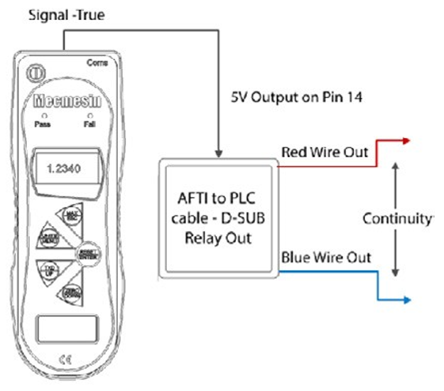
PLC Signals: The output of the pin is high 5V, low 0V
4.32.3 Female 15 way ‘D Type’ Communication Connector Pin Out and Relay Diagram
|
Pin Out: |
|
|
1 |
Analogue Output |
|
2 |
RS232 Transmit |
|
3 |
RS232 Receive |
|
4 |
Digimatic Clock Output |
|
5 |
Digimatic Ready Output |
|
6 |
+5 volts |
|
7 |
FREEZE Reading Input |
|
8 |
Stand Reverse UP |
|
9 out |
Footswitch 2 Input/SMART -ve |
|
10 |
Ground |
|
11 |
Digimatic Request Input |
|
12 |
Digimatic Data Output |
|
13 |
Footswitch 1 Input |
|
14 |
PLC Output |
|
15 |
Stand reverse DOWN |
4.32.4 Relay Electrical
Supply voltage: The relay is powered from a 5V regulator inside the AFG.
Input control: The relay state is controlled via a TTL signal from the AFG and is in a ‘closed position’ when a logic ‘1’ input is applied (Signal from the AFG is true).
4.32.5 Relay Output Characteristics (351-063)
Output Function: Continuity between Red and Blue wire when AFG output logic is 1 (Signal True).
Peak relay ac voltage: 350 V
Continuous relay load current (PEAK AC): 120 mA
Maximum relay peak load current: 300 mA Typical relay contact resistance at 100 mA: 17 (Ohm) Isolation voltage between AFG and relay output: 1500 V ac
4.32.6 Relay Description
Using AFG-PLC cable Part number 351-063. The solid-state relay is mounted on a PCB, which is housed in a 15 pin D-type connector.
Connection to the relay output is via a 5 metre length screened cable. The end of the cable is left with bare wires to allow appropriate termination to the peripheral PLC device.
4.33 Communications Cables
Interface cables for connecting your AFG to peripheral devices:
|
Cable |
Mecmesin Part Number |
|
AFG to RS232 (9-pin D-type) |
351-059 |
|
RS232 (9-pin D-type) to USB converter kit |
432-228 |
|
AFG to Digimatic (Mitutoyo 10-way IDC) |
351-058 |
|
AFG to Analogue |
351-060 |
|
AFG to PLC |
351-063 |
|
AFG to Footswitch 1 |
351-061-vo1 |
|
AFG to Footswitch 2 |
351-061-vo2 |
|
MultiTest-d Stand Reverse and RS232 to AFG Cable |
351-074 |
|
Universal Expansion Module (for connecting up to 5 cables simultaneously) |
432-127 |
4.33.1 Adaptor/Charger Unit
The mains adaptor/charger supplied with the AFG is a constant-current type.
Primary: 230V - 50Hz (110V - 60Hz version also available)
Secondary: 100mA constant current at 9V
Charger output plug: Centre = positive Outer = negative
4.33.2 External ‘Smart’ Sensors - Calibration Principle
Mecmesin use standard mV/V sensors in all instruments. These sensors are subjected to an excitation voltage from the host display (either AFTI or AFG) and the signal is amplified. Due to the ratiometric principle, when the amplified signal is converted from analogue to digital, the excitation voltage (also known as reference voltage) appears on both sides of the conversion equation and therefore cancels itself out. In real terms, the absolute value of the excitation voltage is unimportant to the conversion! Any components that are not subject to the ratiometric principle have been specified within the product design to be high-precision and their allowable deviation falls well within the accuracy tolerance of the instrument. As a consequence of using this technique, it is not necessary to match-calibrate the ‘Smart’ sensor to a specific display. You may only return the ‘Smart’ sensor to Mecmesin or an authorised distributor for calibration.