- 1 Introduction
- 2 Before Use
- 3 Operation
- 4 Maintenance
- 4.1 Assembly of the Orbis
- 4.2 Powering the Orbis
- 4.3 Using the Orbis
- 4.3.1 Fitting accessories
- 4.3.2 Powering up
- 4.3.3 Clockwise and Counter-clockwise Values
- 4.3.4 Zeroing the Orbis
- 4.3.5 Changing the unit of measurement
- 4.3.6 Max (peak) readings
- 4.3.7 ‘Max’ mode
- 4.3.8 Dual Max
- 4.3.9 Max Clockwise Torque
- 4.3.10 Max Counter-clockwise Torque
- 4.3.11 'Normal’ mode
- 4.3.12 Data Output
- 4.4 Optional Settings - ‘Hot Keys’
- 4.5 RS232 Commands Table: Configuration
- 4.6 RS232 Command Responses: Information
- 4.7 Dimensions
- 4.8 Orbis Specifications
- 4.9 Communications Cables
1 Introduction
Thank you for choosing Mecmesin’s Orbis Digital Torque Tester. With correct use and regular re-calibration it will give many years of accurate and reliable service.
The Orbis has been specifically designed as a high-accuracy, portable instrument for measuring clockwise and counter-clockwise torques. Using the latest integrated circuit technology and intuitive programming, the Orbis is easy to use by all operators.
2 Before Use
Upon receiving the unit please check that no physical damage has occurred to the packaging material, plastic case or the instrument itself. If any damage is evident please notify Mecmesin immediately.
3 Operation
The most commonly used features such as displaying torque, peak hold, zero and changing of displayed units can all be done by pressing single dedicated keys on the front panel.
For less frequently used features a number of ‘hot keys’ are provided, whereby the operator simply presses and holds an appropriate key upon startup to enable a gauge option.
4 Maintenance
When cleaning the keypad care must be taken to avoid liquids, especially alcohols, seeping around the edge of the membrane. Therefore, we recommend the use of a lightly dampened cloth to avoid liquid spillage onto the membrane.
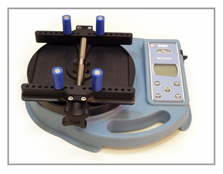
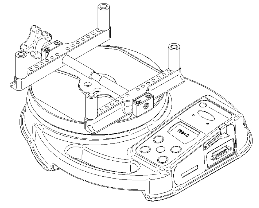
4.1 Assembly of the Orbis
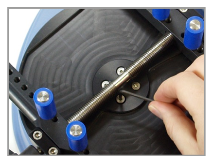
Unscrew the top plate handle so that the peg holders move towards the outside edge of the plate. Align the top plate with the torque drive so that the handle is on the left-hand side of the top plate. Using the 2.5mm Allen key (provided), tighten the four-socket countersunk screws hand tight.
When the Orbis is in transit, the top plate is removed to avoid damage to the torque sensor.
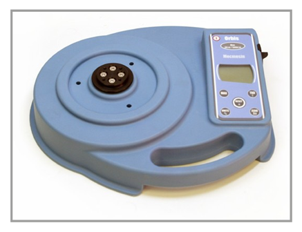
4.1.1 Fitting Instructions for the Orbis Top Plate
Step 1: Orbis with torque drive shown.
Step 2: Align top plate with torque drive. The handle is positioned to the left.
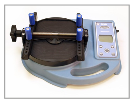
Step 3: Tighten screws hand-tight only.
Step 4: For use of Orbis with handle at front, repeat steps 1 to 3 but position top plate accordingly during step 2.
4.2 Powering the Orbis
The Orbis is supplied with a set of 5 Nickel Metal Hydride AAA rechargeable batteries, which are supplied fully charged to allow use straight from the box. Do not use any other battery charger other than that supplied with the torque tester.
4.2.1 Replacing rechargeable batteries
Under normal circumstances these rechargeable batteries will not need to be replaced. However, if required, to replace the rechargeable batteries you must first remove the base plate on the base of the torque tester by removing the 6 retaining screws. This will reveal a retaining plate.
Remove this by releasing the 2 screws on the retaining plate. Remove the fitted rechargeable batteries and fit the 5 new rechargeable batteries in the battery holder, ensuring that you observe polarity and the batteries are placed on top of the ‘release tag’ and they will be freed from the spring-loaded contacts.
Refit the retaining plate and tighten the 2 screws. Refit the base plate and tighten the 6 retaining screws.
Connect the mains adaptor/charger to the Orbis charger socket located at the right hand side of the torque tester next to the display and charge the new set of rechargeable batteries for 14 - 16 hours. Only use the adaptor/charger supplied. A fully charged battery pack will provide approximately 20 hours constant use between charges.
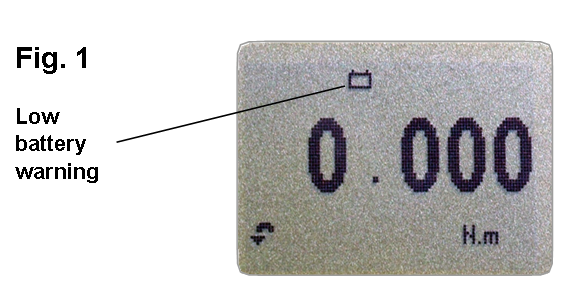
4.2.2 Low battery warning
A low battery symbol will appear in the display approximately 2 minutes before the torque tester powers down automatically. See Fig. 1, below.
4.2.3 Mains operation
The Orbis may also be powered directly from the mains. Simply maintain the mains adaptor/charger connection to your mains supply as above. Only use the adaptor/charger supplied.
4.3 Using the Orbis
The Orbis is supplied with 4 pegs which grip the sample during testing.
4.3.1 Fitting accessories
Screw the pegs into the runners on the top fixture equally spaced to ensure the sample is securely gripped when the runners are brought together using the star handle on the end of the lead screws.
Ensure that the pillars are finger tight and the sample securely clamped, otherwise rotation in the fixture will occur during testing.
4.3.2 Powering up
As shown in Fig. 1, the control panel has 6 keys:
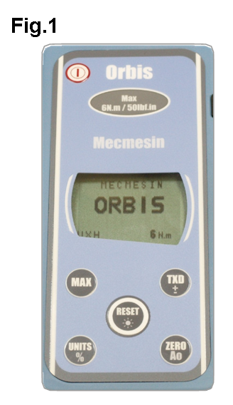
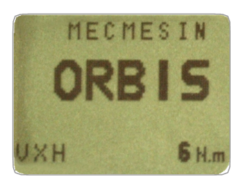
To power up the Orbis press the red ![]() key. A short self test runs during which the display will show the capacity in ‘N.m’ (newton metres).
key. A short self test runs during which the display will show the capacity in ‘N.m’ (newton metres).
After the self test, providing no torque has been applied to the instrument, the display will show all zeros. This is because the Orbis re-zeros itself during the self test routine.
If a torque is applied rotationally via the fixture, the reading on the display will register the applied torque.
* Do not overload the torque sensor, as this could cause irreparable damage.
Loads greater than 120% of full-scale will produce an audible beep until load is released and an OL symbol will appear on the display for 30 seconds.
Loads greater than 150% of full-scale will produce an audible beep until load is released and an OL symbol will appear permanently on the display. Consult your supplier to arrange repair.
![]() To power down the Orbis press the red
To power down the Orbis press the red ![]() key.
key.
4.3.3 Clockwise and Counter-clockwise Values
Clockwise torque is displayed on the Orbis and recognised by the symbol shown in Fig. 2.
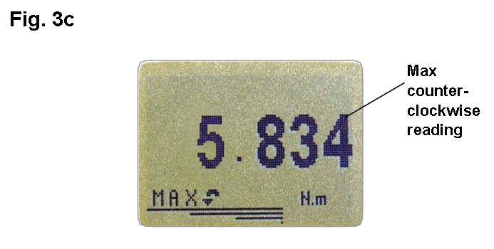
Counter-clockwise torque is displayed on the Orbis and recognised by the symbol shown in Fig. 3c.
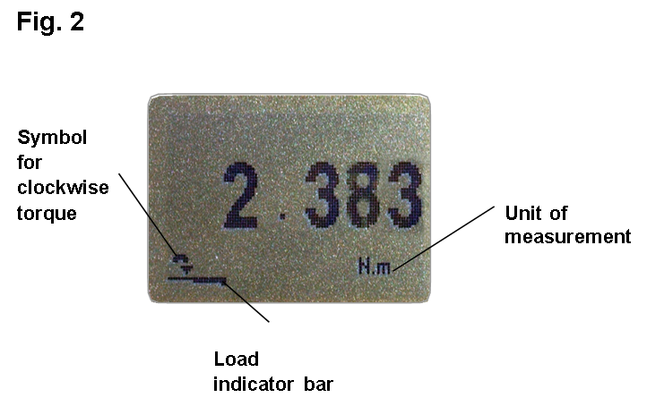
A torque indicator bar alerts the operator to how much load has been applied to the torque sensor. As the load approaches the maximum rating of the torque sensor, the indicator bar changes appearance when above approximately 80% of the rated capacity. This warns the operator that steps should be taken to prevent excessive torque being applied.
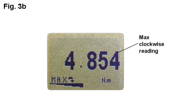
When applying clockwise torque, the indicator bar begins solid in appearance, then becomes striped when the capacity is approached. When applying counter-clockwise torque, the indicator bar begins striped, then becomes solid - see Fig. 3b & 3c.
If the Orbis has suffered a serious overload condition, the torque indicator bar will be partially displayed even when no torque is present. This is a warning that the torque sensor is damaged and you should immediately contact your supplier to arrange repair.
4.3.4 Zeroing the Orbis
During operation of the Orbis, it is sometimes necessary to zero the display - e.g. when you wish to tare out a displayed torque applied by the sample, so it does not become part of the measured reading. Press and release the ZERO key. The display will freeze whilst the key is pressed.
4.3.5 Changing the unit of measurement
You can choose from the following units of measurement: N.m, N.cm, mN.m, gf.cm, kgf.cm, kgf.m, lbf.ft, lbf.in, ozf. in.
To change the displayed units, press and release the UNITS key. Each successive key press will select the next available units until the Orbis returns to its original setting. The Orbis automatically converts readings as new units of measurement are selected.
4.3.6 Max (peak) readings
The Orbis detects and stores maximum (peak) torque in both clockwise and counter-clockwise directions.
4.3.7 ‘Max’ mode
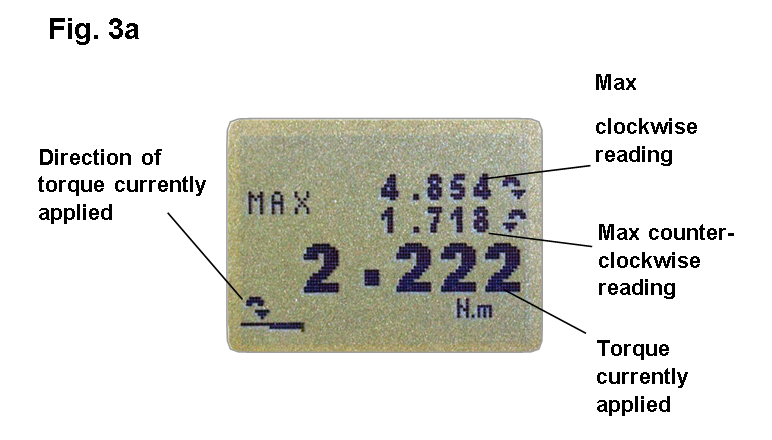
Press the MAX key. The display will show the word MAX together with the highest counter-clockwise torque and the highest clockwise torque detected during the test. The current load being applied to the torque sensor is also displayed - see Fig. 3a
4.3.8 Dual Max
4.3.9 Max Clockwise Torque
Press the MAX key again, and the display will show the maximum clockwise torque identified by its symbol.
4.3.10 Max Counter-clockwise Torque
Press the MAX key again, and the display will show the maximum counter-clockwise torque identified by its symbol.
4.3.11 'Normal’ mode
Press the MAX key again, and the word MAX has now disappeared from the display. The display will now indicate torque of either direction, as it is applied, maintaining a ‘running’ display.
Press the RESET key to clear both maximum registers and prepare for detecting the next maximum readings.
4.3.12 Data Output
The Orbis has RS232, Digimatic and analogue output signals. It is possible to transmit the displayed reading to peripheral devices (e.g. PC, printer) by pressing and releasing the TXD key.
Displayed readings can also be requested individually from a PC via the RS232 interface by sending a “?” character. See page 13. When using the Orbis for creating a graphical presentation of data, ensure that the normal mode, and not a max mode, is selected.
For sending a continuous data stream to a PC, press and hold the TXD key for 2 seconds. TX will now appear in the display to indicate that data is being sent. To stop sending data, simply press and release the TXD key, at which point TX will disappear from the display.
Please note that the continuous data stream only starts when approximately 2% of the rated capacity of the Orbis is reached.
Orbis uses 9600 Baud 8 data bits, 1 start bit 1 stop bit and no parity.
A full range of data cables are available to connect the Orbis to peripheral devices. Please contact your supplier for further information.
4.4 Optional Settings - ‘Hot Keys’
4.4.1 Backlit Display
It is possible to activate a back-light on the Orbis display. Press and hold RESET whilst powering up the Orbis with the ![]() key. The back-light is now operating.
key. The back-light is now operating.
Please note that battery consumption is doubled when using the back-light.
4.4.2 Auto-off
To conserve battery power, it is possible to activate an Auto-off function. This causes the Orbis to power down automatically 5 minutes after the last key press, or 5 minutes after the last application of a torque greater than 2% of full capacity.
Press and hold ZERO whilst powering up the Orbis with the ![]() key. The symbol ‘Ao’ will appear in the display to indicate Auto-off is active.
key. The symbol ‘Ao’ will appear in the display to indicate Auto-off is active.
4.4.3 Invert Display
It may be desirable to invert the display, so that it may be easily read upside down. By pressing and holding MAX whilst powering up the Orbis with the ![]() key, the display is inverted.
key, the display is inverted.
4.4.4 Locking and unlocking ‘Max’ mode
Once the desired Max display mode has been selected, it is possible to lock the mode, so that further pressing the MAX key results in no change.
Press and hold RESET and MAX keys simultaneously whilst powering up the Orbis with the ![]() key. ‘MAX KEY LOCKED’ will appear on the display until the ‘Hot Keys’ are released. The Max display mode is now locked.
key. ‘MAX KEY LOCKED’ will appear on the display until the ‘Hot Keys’ are released. The Max display mode is now locked.
To unlock the Max display mode, repeat as above. ‘MAX KEY UNLOCKED’ will appear on the display until the ‘Hot Keys’ are released.
4.4.5 Locking and unlocking the unit of measurement
Once the desired unit of measurement has been selected, it is possible to lock the units, so that further pressing the UNITS key results in no change.
Press and hold RESET and UNITS keys simultaneously whilst powering up the Orbis with the ![]() key. ‘UNITS KEY LOCKED’ will appear on the display until the ‘Hot Keys’ are released. The units are now locked.
key. ‘UNITS KEY LOCKED’ will appear on the display until the ‘Hot Keys’ are released. The units are now locked.
To unlock the units, repeat as above. ‘UNITS KEY UNLOCKED’ will appear on the display until the ‘Hot Keys’ are released.
4.4.6 Removal of minus sign for counter-clockwise (release torque) measurements
To differentiate between clockwise and counter-clockwise measurements when transmitted to peripheral devices, counter-clockwise results may be prefixed with a minus sign. Press and hold the TXD key whilst powering up the Orbis with the ![]() key. The display will show TX SIGN OFF and ON. This will transmit a negative sign for counter-clockwise readings if set to ON. Use the TXD key to position the arrow cursor against the desired selection and press the RESET key. The display will continue to the main menu.
key. The display will show TX SIGN OFF and ON. This will transmit a negative sign for counter-clockwise readings if set to ON. Use the TXD key to position the arrow cursor against the desired selection and press the RESET key. The display will continue to the main menu.
4.4.7 Torque Sensor Diagnostic test
If you suspect that your torque sensor has sustained an overload, it is possible to check the status of the torque sensor immediately.
Symptoms of overload may be (a) OL in display (b) buzzer sound (c) torque indicator bar present even under zero load.
Place the Orbis horizontally on a flat, level surface. Press and hold the UNITS key whilst powering up the Orbis with the ![]() key.
key.
The torque sensor diagnostic test screen will appear on the display, as shown in Fig. 4.
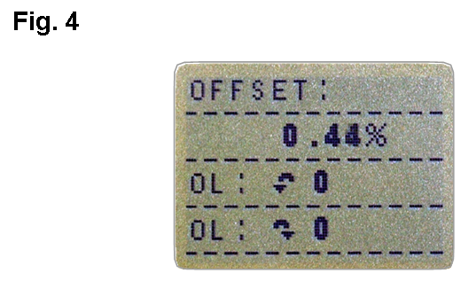
The offset value provides an indication of the condition of the torque sensor, and is defined as the % difference between the critical zero and the current reading.
If the offset is between 5 - 10 %, please contact your supplier to arrange a re-calibration of your Orbis.
If the offset is greater than 10 %, please contact your supplier to arrange for a torque sensor replacement.
These values are given as an indicator only - the need for calibration/repair may vary according to the individual characteristics of the torque sensor.
In addition to the offset, the number of overloads (OL) experienced by the torque sensor in both clockwise and counter-clockwise directions are displayed. An overload is registered when a torque exceeding 150% of the rated capacity of the torque sensor is applied in either direction. To exit the torque sensor diagnostic test screen, press MAX.
4.5 RS232 Commands Table: Configuration
It is possible to remotely configure the setting of your Orbis by sending the following RS232 command characters:
|
Character in ASCII |
Decimal |
Hexadecimal |
Function |
|
M |
77 |
0x4D |
Current mode |
|
U |
85 |
0x55 |
Current units |
|
C |
67 |
0x43 |
Torque sensor capacity |
|
@ |
64 |
0x40 |
Configuration status request |
|
* |
42 |
0x2A |
Continuous transmit |
|
r |
114 |
0x72 |
Normal Screen |
|
s |
115 |
0x73 |
Dual Max |
|
t |
116 |
0x74 |
Max Clockwise |
|
u |
117 |
0x75 |
Max Counter-clockwise |
|
a |
97 |
0x61 |
N.m |
|
b |
98 |
0x62 |
N.cm |
|
c |
99 |
0x63 |
mN.m |
|
d |
100 |
0x64 |
gf.cm |
|
e |
101 |
0x65 |
kgf.cm |
|
f |
102 |
0x66 |
kgf.m |
|
g |
103 |
0x67 |
ozf.in |
|
h |
104 |
0x68 |
lbf.ft |
|
i |
105 |
0x69 |
lbf.in |
|
? |
63 |
0x3F |
Transmit the current reading |
|
CTRL a |
1 |
0x01 |
TXD key |
|
CTRL b |
2 |
0x02 |
UNITS key |
|
CTRL c |
3 |
0x03 |
MAX key |
|
CTRL d |
4 |
0x04 |
RESET key |
|
CTRL e |
5 |
0x05 |
ZERO key |
4.6 RS232 Command Responses: Information
It is possible to remotely interrogate your Orbis by sending the following RS232 commands. This will inform you which settings are currently configured.
4.6.1 Command: M
|
Response |
Orbis Display Mode |
|
Normal |
Normal Mode |
|
MaxC |
Max Counter-clockwise |
|
MaxT |
Max Clockwise |
|
MaxDual |
Dual Max Screen |
4.6.2 Command: U
|
Response for Torque Sensor |
|
N.m |
|
N.cm |
|
mN.m |
|
gf.cm |
|
kgf.cm |
|
kgf.m |
|
lbf.ft |
|
lbf.in |
|
ozf.in |
4.6.3 Command: C
The torque sensor size, in the current selected units.
Note: ‘xxxx’ will be transmitted if the torque sensor is not calibrated or has a serious fault. Contact Mecmesin or your supplier.
4.6.4 Command: @
When all options are OFF, and the Orbis is set at defaults, you will receive the following information listing:
|
Response |
Explanation of Response |
|
ORBIS |
Gauge type |
|
6N.m |
Torque sensor size in N.m as per transmitting ‘C’ |
|
V01 |
Version number |
|
Normal |
Mode of operation as per transmitting ‘M’ |
|
Function |
Default Setting |
|
TXD -SIGN |
OFF |
|
BACKLIGHT |
OFF |
|
AUTO-OFF |
OFF |
|
INVERT |
OFF |
4.6.5 TXD-SIGN 1 options explained below:
|
TXD-SIGN 1 |
|
|
1 |
Transmit minus sign, ON or OFF |
4.6.6 BACKLIGHT 1 options explained below:
|
BACKLIGHT 1 |
|
|
1 |
Backlight enabled, ON or OFF |
4.6.7 AUTO-OFF 1 options explained below:
|
AUTO-OFF 1 |
|
|
1 |
Auto-off time, OFF or 5 mins |
4.6.8 INVERT 1 options explained below:
|
INVERT 1 |
|
|
1 |
Display inverted, ON or OFF |
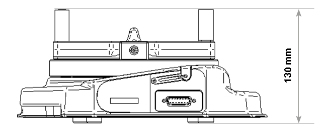
4.7 Dimensions
4.7.1 Side View
4.7.2 Top View
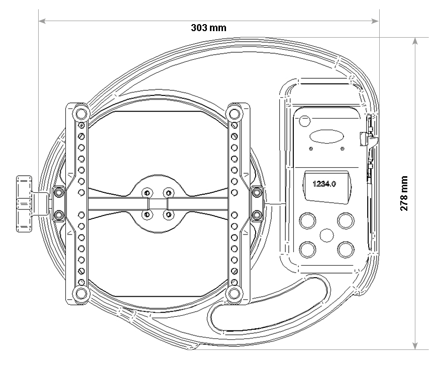
* Min-Max opening: 10 - 190mm diameter
4.8 Orbis Specifications
4.8.1 Range & Units Of Measurement
Ranges: 0 - 6N.m, 0 - 60kgf.cm, 0 - 53lbf.in
Units: N.m, N.cm, mN.m, gf.cm, kgf.cm, kgf.m, lbf.ft, lbf.in, ozf.in
4.8.2 Accuracy
±0.5% of full scale
Calibration temperature: 20°C ±2°C
Operating temperature: 10°C - 35°C
Temperature shift at zero load: ±0.01% of full-scale/°C
4.8.3 Output
|
9600 baud rate, 8 data bits, 1 Start bit, 1 Stop bit, no parity 0V at zero load, approximately ±1.5V uncalibrated for full-scale clockwise/counter-clockwise |
4.8.4 Adaptor/Charger Unit
The mains adaptor/charger supplied with the Orbis is a constant-current type.
Primary: 230V - 50Hz (110V - 60Hz version also available)
Secondary: 100mA constant current at 9V Charger
output plug: Centre = positive Outer = negative
4.8.5 Water Resistance
The Orbis is rated to IP54 water resistance.
Note: This IP rating is only valid when no charger or comms cables are connected, and the charger socket cap and comms connector cover are in place.
4.9 Communications Cables
![]() Interface cables for connecting your Orbis to peripheral devices:
Interface cables for connecting your Orbis to peripheral devices:
|
Cable |
Mecmesin Part Number |
|
Orbis to RS232 (9-pin D-type) |
351-059 |
|
RS232 (9-pin D-type) to USB converter kit |
432-228 |
|
Orbis to Digimatic (Mitutoyo 10-way IDC) |
351-058 |
|
Orbis to Analogue |
351-060 |
Allocation for the pins on the male 15 way ‘D Type’ Communication Connector:
|
Pin Out: |
|
|
1 |
Analogue Output |
|
2 |
RS232 Transmit |
|
3 |
RS232 Receive |
|
4 |
Digimatic Clock Output |
|
5 |
Digimatic Ready Output |
|
6 |
not used |
|
7 |
not used |
|
8 |
not used |
|
9 |
not available |
|
10 |
Ground |
|
11 |
Digimatic Request Input |
|
12 |
Digimatic Data Output |
|
13 |
not used |
|
14 |
not used |
|
15 |
not used |