1 Designing a Test (VectorPro Lite Version)
 |
431-955 February 2020 |
2 Introduction
VectorPro™, VectorPro™ MT and VectorPro™ Lite are all registered trademarks of Mecmesin Ltd.
VectorPro is a dedicated software solution used for the programming and acquisition of data from a range of Mecmesin test stands and instruments.
2.1 User Guidance
This user manual section covers designing for VectorPro Lite compatible instruments only, for further guidance relating to other aspects of VectorPro please refer to one of the documents listed below.
2.1.1 VectorPro™ User Manuals
Click one of the links below to navigate to the applicable user manual.
 |
 |
 |
A detailed guide to designing a test for VectorPro MT compliant test systems. |
|
Designing a Test Lite Version (Current Document) Covers designing a test for VectorPro Lite compliant test stands and devices |
 |
 |
All Tests Viewer and Results Viewer A guide explaining the functionality of the All Tests Viewer and Results Viewer. |
 |
 |
|
View the latest version of the Mecmesin VectorPro Software License Agreement. |
- 1 Designing a Test (VectorPro Lite Version)
- 2 Introduction
- 3 Designing a Test - Getting Started
- 4 Attributes
- 5 Operations
- 6 Result
- 7 Report
- 8 Permissions
- 9 Saving a Test
- 10 Further Information
3 Designing a Test - Getting Started
Click the ‘New Test’ tile to configure a new test. The ‘New Test’ screen, pictured above, is displayed onscreen. Select your instrument from either the main 'All' tab or filtered view, e.g. 'Force'. Within this tab select the desired test system or model.
3.1 Test Names and Versions
Click the ‘New Test’ tile to configure a new test. The ‘New Test’ screen, pictured below, is displayed onscreen. The instruments displayed can be filtered using one of the tabs located at the top of the window.
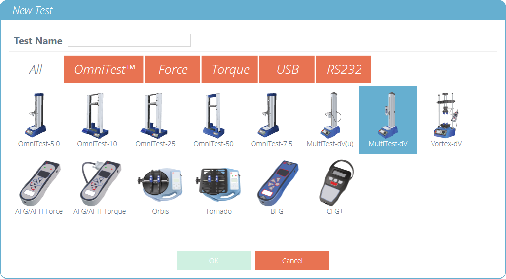
The ‘New Test’ selection screen, select which instrument is used.

A new test contains a series of settings tabs; Attribute configuration, a sequential Operations (USB Test Systems Only), Result calculations, an optional editable Report layout and Permissions specific to this test.
4 Attributes
Attributes extend the information about a test. Some are reserved by default and others are customisable. The ‘System’ attribute, for example, is not editable and is available in results and reports to indicate the test system used for the test. When a new test is first created, two attributes are automatically added. ‘Test Name’ entered from the new test screen and a blank ‘Test Notes’ attribute.
Attributes can be added to store notes, labels or attach images to the test. Attributes can be configured to prompt for input value before or after the test.
Icons for a ‘Label’, ‘Note’ and an ‘Image’ attribute.
4.1 Test Name
Default attribute
Names the test routine and all versions. This attribute can be edited but is in all versions of the test, not just subsequent versions.
4.2 Test Notes
Default attribute
Applies to this test version, and is inherited by subsequent versions until amended again.
4.3 Add New and Existing Custom Attributes
Once an attribute has been used in VectorPro, it is incorporated into the database and becomes available to all tests under the existing attribute section. An attribute must have a unique name and can be a ‘label’ (up to 30 characters), a ‘note’ (up to 300 characters) or an 'image'.
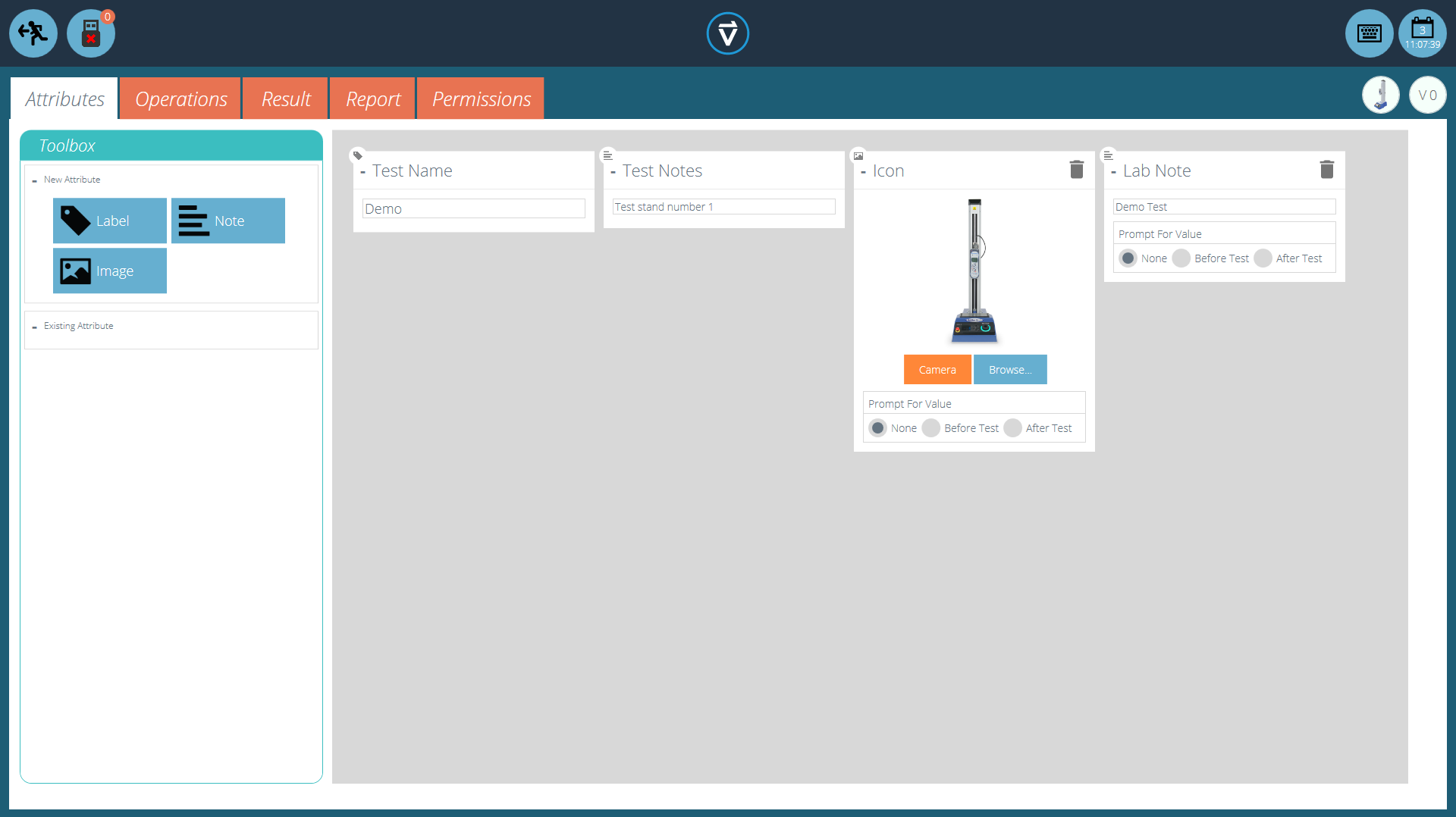
Icons for a ‘Label’, ‘Note’ and an ‘Image’ attribute.
Image attributes allow the insertion of an image file, which may be browsed for, or captured on a webcam. The first image to be assigned appears as the ‘Workspace’ icon for this test (attributes for a test, once assigned, cannot be rearranged).
Image and note attributes also have a ‘Prompt for Value’ setting. Options available are:
- None: No action is prompted before or after the test, fixed image or note can be entered here,
- Before Test: The user is prompted for an image file or note before the test,
- After Test: The user is prompted for an image file or note after the test,
4.4 Prompt for Value Feature
Within VectorPro, attributes can be configured to prompt for input value before or after the test is run.
This can be applied to a note, label or image attribute which enables the test to prompt the user for input before or after testing. These labels are then saved to the relevant result file. This is shown below whereby a ‘Batch ID’ label has been set up with a before test prompt and a ‘Lab Temperature’ label has been set up with an after test prompt.
In the example screenshot below when editing or creating a test, the image and note attributes have the option to configure ‘before’ or ‘after’ test options. For example, this can be useful for logging important notes or for adding pictures of the specimen pre-test and post-test.
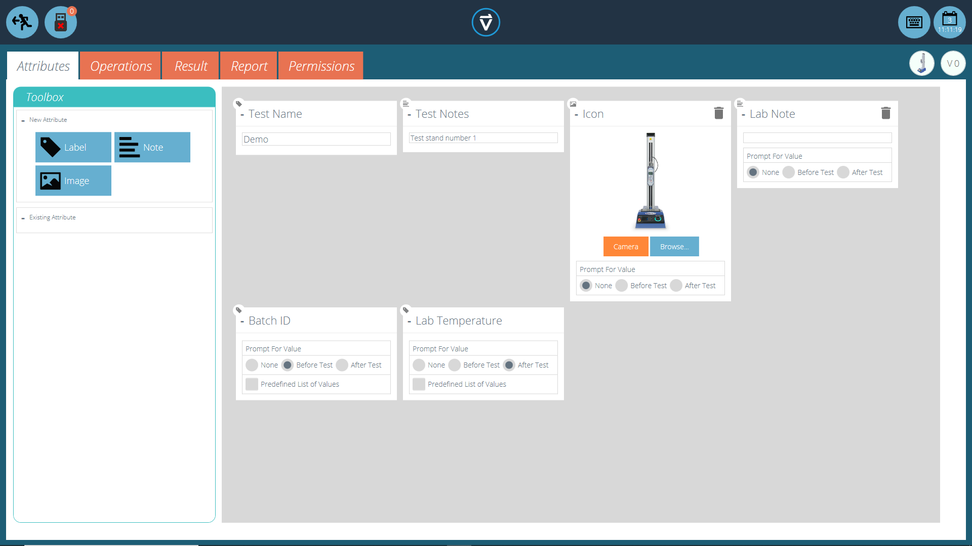
This image shows the ‘prompt for’ settings highlighted by the red circle.
4.4.1 Prompt for Value – Flag Definitions
Prompt for Value attributes carry flag markers to give easy visual identification to whether they are before or after the test values. These markers are visible in the ‘Results’ tab when both within the ‘Test Designer’ and the ‘Results Viewer’.
A diagram displaying the new flag markers. The left-hand icons are the markers within the ‘Results’ design page and the right hand are within the ‘Results Viewer'. Before test flags are highlighted in blue and after test flags are highlighted in green.
4.4.2 Prompt for Value - Predefined List
Label attributes using the ‘Prompt for Value’ feature can be set up with a predefined list. For example, these lists could be used to state batch numbers or the colours of the test specimens.
To use the predefined list feature the user must first create a new label attribute, then select the ‘Predefined List of Values’ option to display the input table. Enter the values by pressing ‘Add’ and remove unwanted values by pressing ‘Remove’.
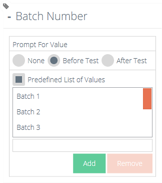
In the example shown both above and below a label attribute called ‘Batch Number’ is configured within the test designer with ‘Before Test’ selected and a predefined list of batch numbers entered.
Upon starting the test, the ‘Prompt for Value – Before Test’ window appears. Entry input is available, for any attributes that have been configured to prompt before the test is run.
4.5 Grouping Attributes - Creating Test Folders
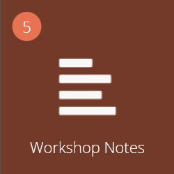
Grouped attribute tile.
Within VectorPro it is possible to assign the same attribute to several tests so it can be used as a filter to group tests together on the main ‘Workspace’ screen.
This allows for easy grouping of tests based on a common image, note or label. These tests are then grouped into a brown tile like the one pictured above. The following pages detail how to achieve this.
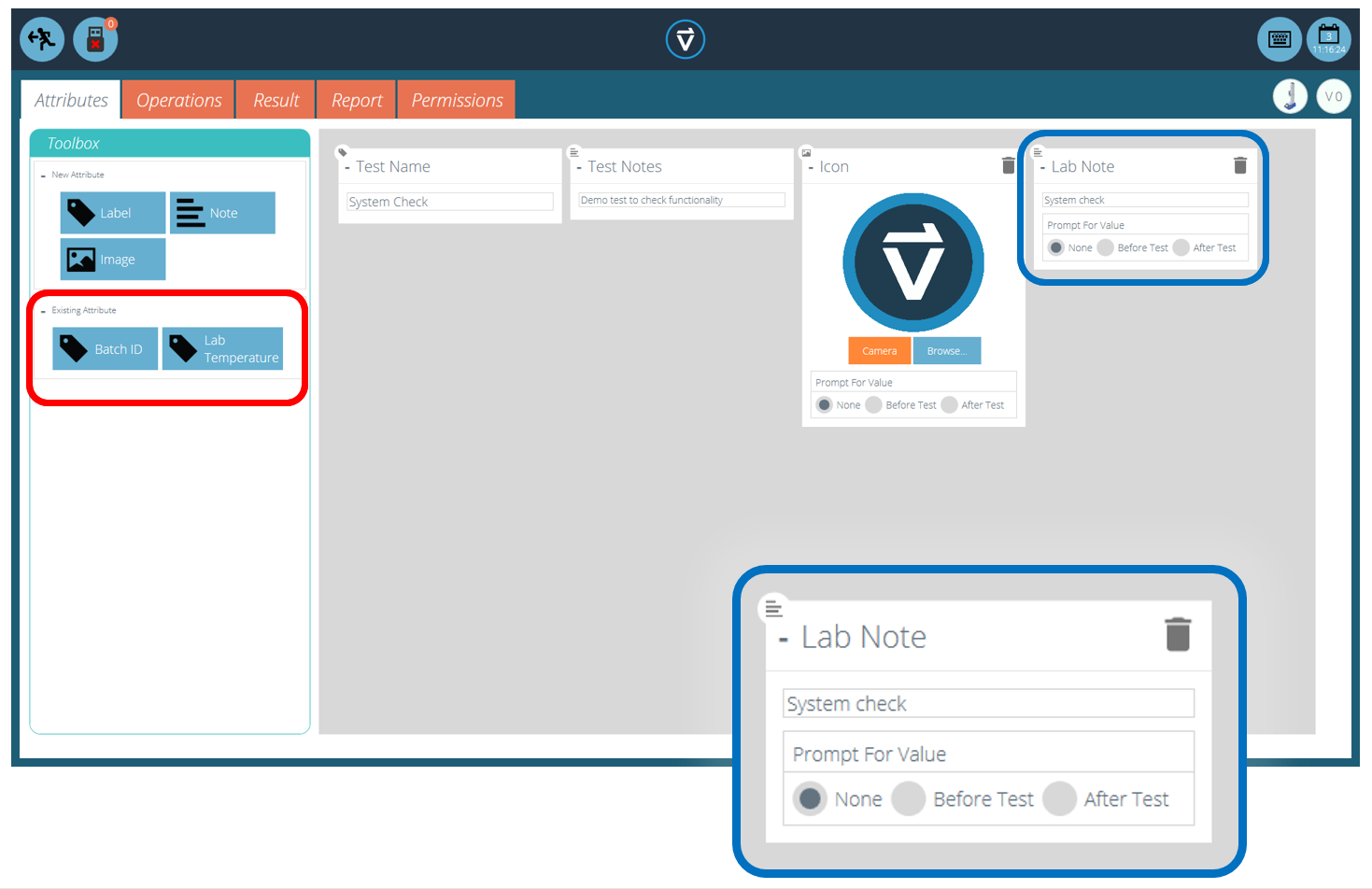
Within the relevant test, place the desired attribute. For example, in the screen above an attribute called ‘Lab Notes’ is being used by the operator to describe the test being executed. Previously used attributes can be found in the ‘Existing Attributes’ section (highlighted in red).
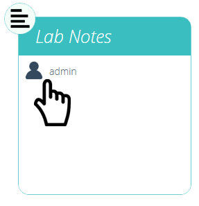
Editing the attribute permissions.
Next, exit the test being edited and click on the ‘Permissions Tile’ located on the far left of the home ‘Workspace’. From here drag-and-drop the relevant user into the specified attribute tile (See the image above).
Attribute tiles are located at the bottom of the ‘Permissions’ screen, below the test system tiles. Use the filter toolbar to show only attributes. In this example above, ‘admin’ has been given rights to see all tests using the ‘Lab Notes’ attribute.
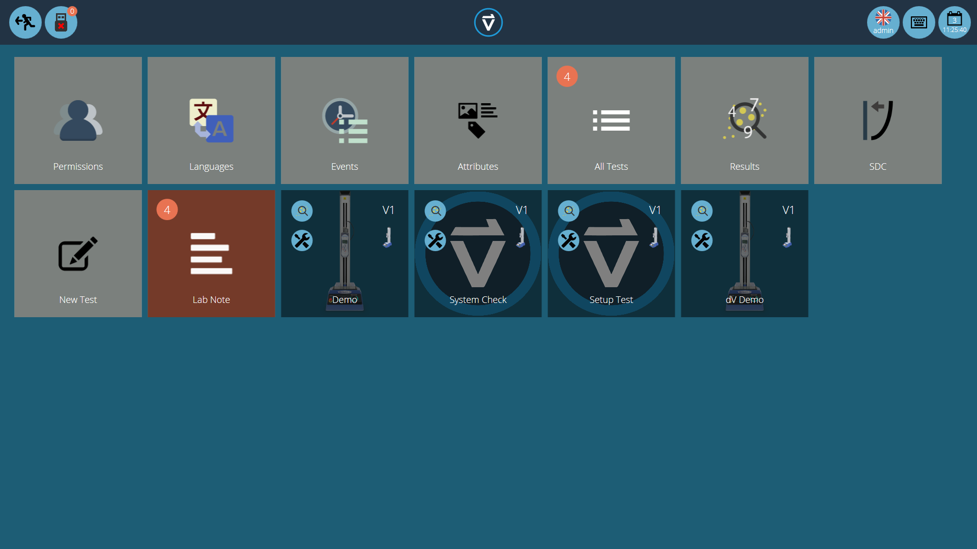
Now the attribute group is present in the home ‘Workspace’ for the admin user to see. For users running a large number of projects, test definitions can be organised into groups only, removing individual test tiles. Therefore helping to organise the screen to maximise the efficiency of the ‘Workspace’.
To achieve this, click edit on the test required to be made invisible, then navigate to the permissions tab and remove the relevant user from the ‘Workspace’ attribute. In this case, as the admin wishes to hide the test, this user is removed from the ‘Workspace’ tile by simply dragging and dropping the user into the trash, as pictured above.
In the second image below, the test files are only visible within the ‘Lab Notes’ attribute group. In this scenario, the workspace rights for admin have been removed from all test files but as the tests contain the ‘Lab Notes’ attribute (which admin has permission for) the tests appear as an organised folder instead of individual tiles.
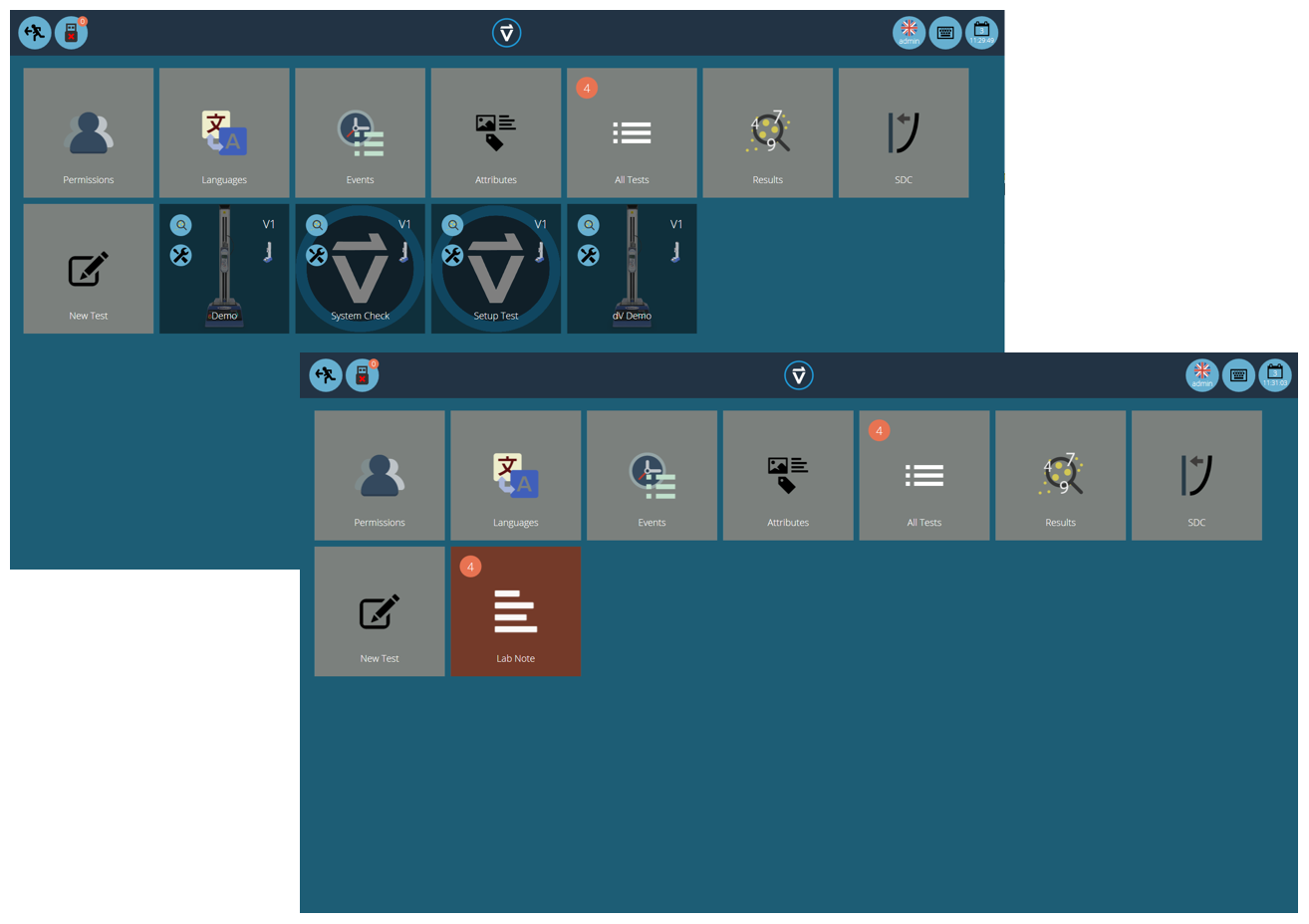
Two workspaces using the same database, the lower has used permissions grouping for each individual test to create a subfolder with all the tests in.
4.6 Searching Within Attribute Groups
Within VectorPro the user can search within the created ‘Attribute Groups’. To access this feature click on a brown group tile that is either linked by a note or label attribute to open the window pictured below (search is unavailable on groups linked by image attributes).
Here, all the tests which contain the ‘Lab Notes’ attribute can be seen. The user can then search using the bar at the top of the window as well as using filters for prompt for value settings (None/Before Test/After Test). Clicking 'Advanced' presents the following search options:
- All (left-hand side): Search all attribute types.
- Label: Search only for label attributes.
- Note: Search only for note attributes.
- Image: Search only for image attributes.
- All (right-hand side): Display all attribute types.
- In Use: Display only attributes that are currently in use.
- Not in Use: Display only attributes that exist in one or more test files, but are not currently in use.
- Ready to delete: Display only attributes that are not in use and were created in a deleted test file.
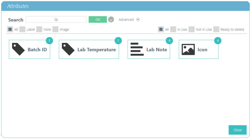
Once a test attribute value is selected, the user is presented with the following options at the bottom of the window:
- Details: Opens an isolated view of the attribute and displays the 'All', 'Results', 'Edit', 'Execute', 'Back' and 'Close' options at the bottom of the window.
- All: Will show the selected attributes test within the ‘All Tests’ viewer. This is to explore the test settings, operations, results and versioning.
- Results: Displays the selected attributes test within the ‘Results’ viewer. Users can view and delete the test results here as well as being able to compare different tests and versions.
- Edit: This opens the selected test in the test designer screen.
- Execute: Clicking ‘Execute’ loads the operation sequence to the test system and opens the test display screen.
- Back: Returns to the previous screen.
- Close: Closes the window.
5 Operations
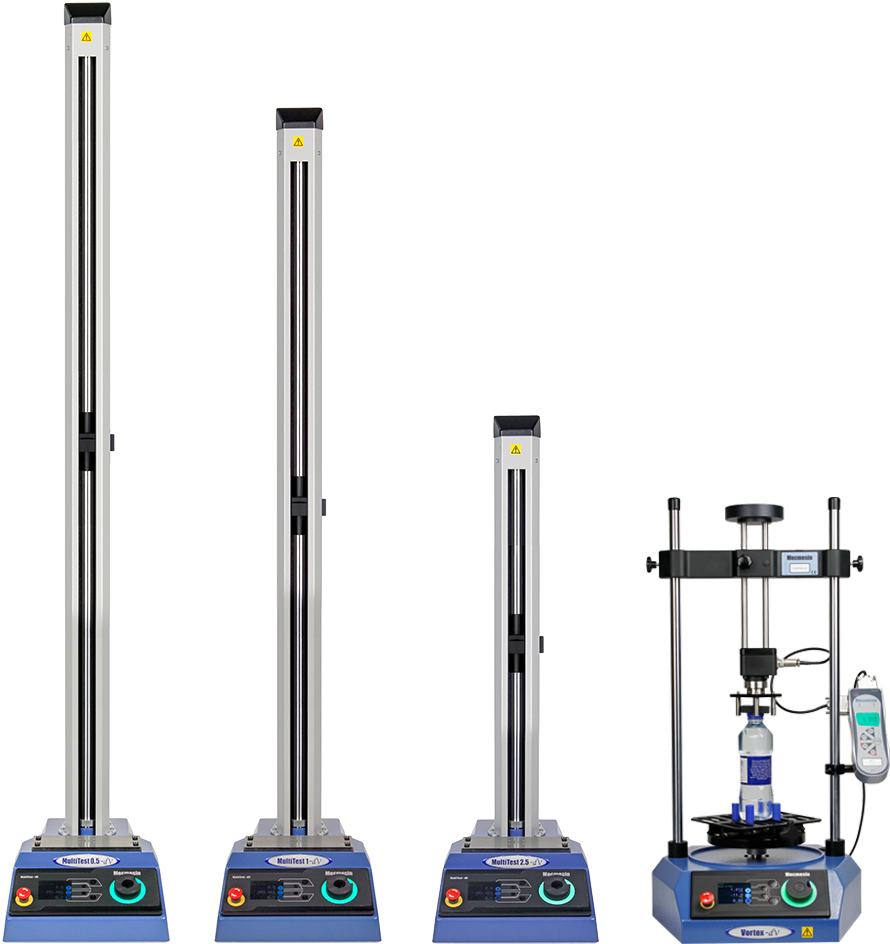
The ‘Operations’ screen defines the single control operation and its user-defined parameters. The system works using drag-and-drop actions, to move operations from the left-hand pane window into the timeline. These commands can be edited to enable the user to run a vast array of tests. This section is only applicable for VectorPro Lite motorised test stands.
Within this section, the operations are defined for MultiTest-dV and Vortex-dV test stands only.
5.1 MultiTest-dV Operation Definitions
|
Icon |
Action |
Settings |
|---|---|---|
|
|
Cycle between two positions with the initial direction towards the base of the stand |
|
|
|
Cycle between two positions with the initial direction towards the top of the stand |
|
|
|
Move the crosshead between physical limit switches. The first direction of movement is down |
|
|
|
Move the crosshead between physical limit switches. The first direction of movement is up |
|
|
|
Moves down to a load limit, or break point, as set by either the AFG gauge or front panel. Also allows cycle control between loads. Starting direction is downward. See section 'Setting Force/Torque Stand Control' for more information. |
|
|
|
Moves up to a load limit, or break point, as set by either the AFG gauge or front panel. Also allows cycle control between loads. Starting direction is upwards. See section 'Setting Force/Torque Stand Control' for more information. |
|
|
|
Moves the crosshead down at a constant speed |
|
|
|
Moves the crosshead up at a constant speed |
|
5.1.1 MultiTest-dV Operation Sequence and Move to Start
MultiTest-dV operations, such as the full and half cycle, consist of two datum points; a minimum and maximum. For operations with the main direction being downward the following is true:
- The ‘Maximum’ is the start position for the test and the ‘Minimum’ is the finishing position.
For operations with the main direction being up the following is true:
- The ‘Minimum’ position is the start position for the test and the ‘Maximum’ is the finishing position.
Within the ‘Edit Test’ menu of the test stand’s front panel there is an option called ‘Move to Start’. Setting this feature to ‘Yes’ means that the stand will always move to the start position defined. In some instances, this means the first direction of movement is opposite to the main test movement. With this feature set to ‘No’ the stand moves straight to the finishing position defined.
5.2 Vortex-dV Operation Definition
|
Icon |
Action |
Settings |
|---|---|---|
|
|
Moves between a starting position and an end position. The first direction of movement is clockwise. |
|
|
|
Moves between a starting position and an end position. The first direction of movement is anticlockwise. |
|
|
|
Moves clockwise to a torque limit or break condition. Control parameters are set using the test stands front panel or AFG. Also allows cyclic between torque points. See section 'Setting Force/Torque Stand Control' for more information. |
|
|
|
Moves anti-clockwise to a torque limit or break condition. Control parameters are set using the test stands front panel or AFG. Also allows cyclic between torque points. See section 'Setting Force/Torque Stand Control' for more information. |
|
|
|
Move to an angle in a clockwise direction |
|
|
|
Move to an angle in an anti-clockwise direction |
|
5.2.1 Vortex-dV Operation Sequence and Move to Start
Vortex-dV operations, such as the full and half cycle, consist of two datum points; a minimum and maximum. For operations with the main direction being downward the following is true:
- The ‘ACW Angle’ is the start position for the test and the ‘CW Angle’ is the finishing position defined.
For operations with the main direction being up the following is true:
- The ‘CW Angle’ is the start position for the test and the ‘ACW Angle’ is the finishing position defined.
Within the ‘Edit Test’ menu on the test stand’s front panel there is an option called ‘Move to Start’. Setting this feature to ‘Yes’ means that the stand will always move to the start position defined.
In some instances, this means the first direction of movement is opposite to the main test movement. With this feature set to ‘No’ the stand moves straight to the finishing position defined.
5.3 Creating a Test Sequence
The ‘Timeline’ allows drag-and-drop of the selected operation command from the left-hand ‘Toolbox’ to define the test function. In this instance the user has chosen to run a test that consists of:
- Full cycle operation that runs from 0mm displacement up to 75mm displacement. The up speed it 250mm/min and the down speed is 1200mm/min.
This test operation can be seen in the blue highlighted box in the image above.
- To remove an operation from the timeline simply drag-and-drop the icon into the centre ‘trash’ icon.
- Alternatively, click the right-hand blue ‘trash’ icon.
5.4 Editing an Operation’s Settings
To edit the operations above simply hover the mouse over the desired operation then click the green symbol once it appears. This action opens the ‘Edit’ menu (pictured below), which is used to configure the operation.
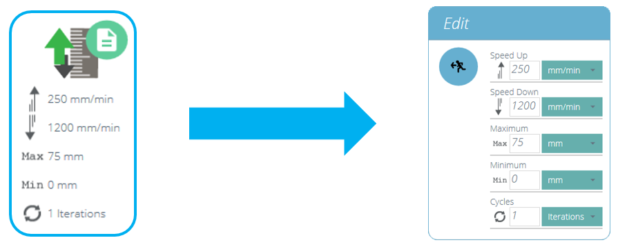
Every operation has parameters that can be edited. Such as displacement, target load, hold time and speed. Below is an example of an operation edit window; this is for a load based drive stage.
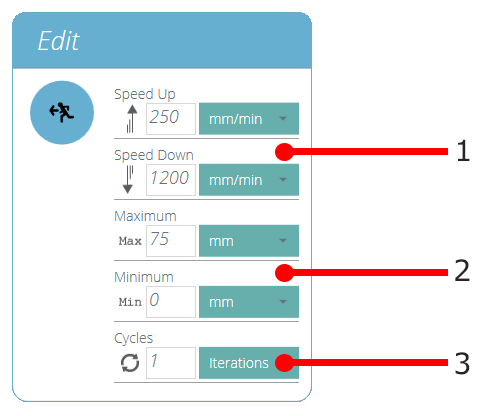
| 1 | These are the speed settings for the up and down movements |
|---|---|
| 2 | These are the settings for the minimum and maximum target displacements |
| 3 | This sets the number of the cycles (iterations) for the operation |
5.5 Setting Force/Torque Stand Control
For MultiTest-dV and Vortex-dV force/torque control tests settings are configured using the front panel and/or an attached AFG/AFTI gauge.
To use these tests in conjunction with VectorPro first, open the settings menu using the test stand’s front panel, then select ‘Edit Test’ and ensure the test type is set to ‘AFG/AFTI Control’.
Under force/torque control there are three test sub-types, these are detailed below along with the accompanying settings:
- AFG/AFTI Control - Control of the test stand using the AFG/AFTI’s limit or break settings. Settings: limit force/torque and stop/reverse.
- Force/Torque Limit – Move in the configured direction until a force/torque limit is reached and then stop. Settings: limit force/torque.
- Force/Torque Cycle – Cycle between a limit force/torque and a return force/torque. Settings: limit force/torque, return force/torque and number of cycles.
- Move to Break – Move in the configured direction until a break condition is detected. Settings: break threshold (percentage of the load/torque cell’s capacity that the test value needs to be above for a break condition to be detected).
Within this menu there are the following common settings:
- Up/Clockwise Speed – Set the upward or clockwise speed, this can also be configured within VectorPro.
- Down/Anti-clockwise Speed – Set the downward or anti-clockwise speed, this can also be configured within VectorPro.
- Start Direction – Select the test start direction, this must match the operation selected in VectorPro.
- Test Sub-Type – Select the test subtype.
5.5.1 AFG Limits
Please note if any force or break limits are set within the AFG gauge, these remain active and can stop the test stand if triggered. If using force control it is recommended that all AFG limit settings are reviewed.
5.5.2 Configuring an AFG/AFTI Control Test
With an additional cable (351-092), the latest model, Mecmesin AFG/AFTI digital force gauge can be used to set load/torque limits to control crosshead movement.
Load setpoint, action (reverse/stop) are all set on the gauge. The stand can then be set to move to a set load or break condition and stop. For more information, please refer to the AFTI/AFG user manual.
5.5.2.1 Example Test Setup
In the test stand’s front panel under ‘Edit Test’ select the test type ‘AFG/AFTI Control’ and sub-type ‘AFG/AFTI Control’.
Configure the speed and direction settings located within the ‘Edit Test’ menu.
In page one of the AFG/AFTI menu select ‘STAND’ using the 'RESET/ENTER' button.
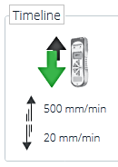
Within VectorPro create a new test, select the AFG/AFTI operation (See the image to the right, MultiTest-dV shown) and ensure the speed and start direction match the settings configured within the test stand in step 2.
Save the test and select the corresponding test icon on the workspace. At this point the test start direction and speed, as set in VectorPro, are uploaded to the stand.
Press play to start the test, the current AFG/AFTI settings are used to control the test limits with the speed and direction settings coming from VectorPro.
5.5.3 Configuring a Force/Torque control Test
Force/torque control tests can be used to set load/torque limits or a break condition to control crosshead movement.
As per the AFG/AFTI control tests these are accessed within the stand’s front panel under the ‘AFG/AFTI Control’ test type but these tests do not use AFG/AFTI settings and are configured using the test stand’s front panel. Within this test type there are three force/torque control sub-tests:
- Force Limit -Move in the configured direction until a force limit is hit and then stop.
- Force Cycle - Cycle between a limit force and a return force.
- Break - Move in the configured direction until a break condition is detected.
For more information please refer to the Vortex-dV or MultiTest-dV user manual.
5.5.3.1 Example Test Setup

Within VectorPro create a new test, select the AFG/AFTI operation (See image to the right, MultiTest-dV shown) and ensure the speed and start direction match the settings configured within the test stand in step 2.
Save the test and select the corresponding test icon on the workspace.
At this point the test start direction and speed, as set in VectorPro, are uploaded to the stand.
Press play to start the test, the current stand settings are used to control the test limits with the speed and direction settings coming from VectorPro.
6 Result
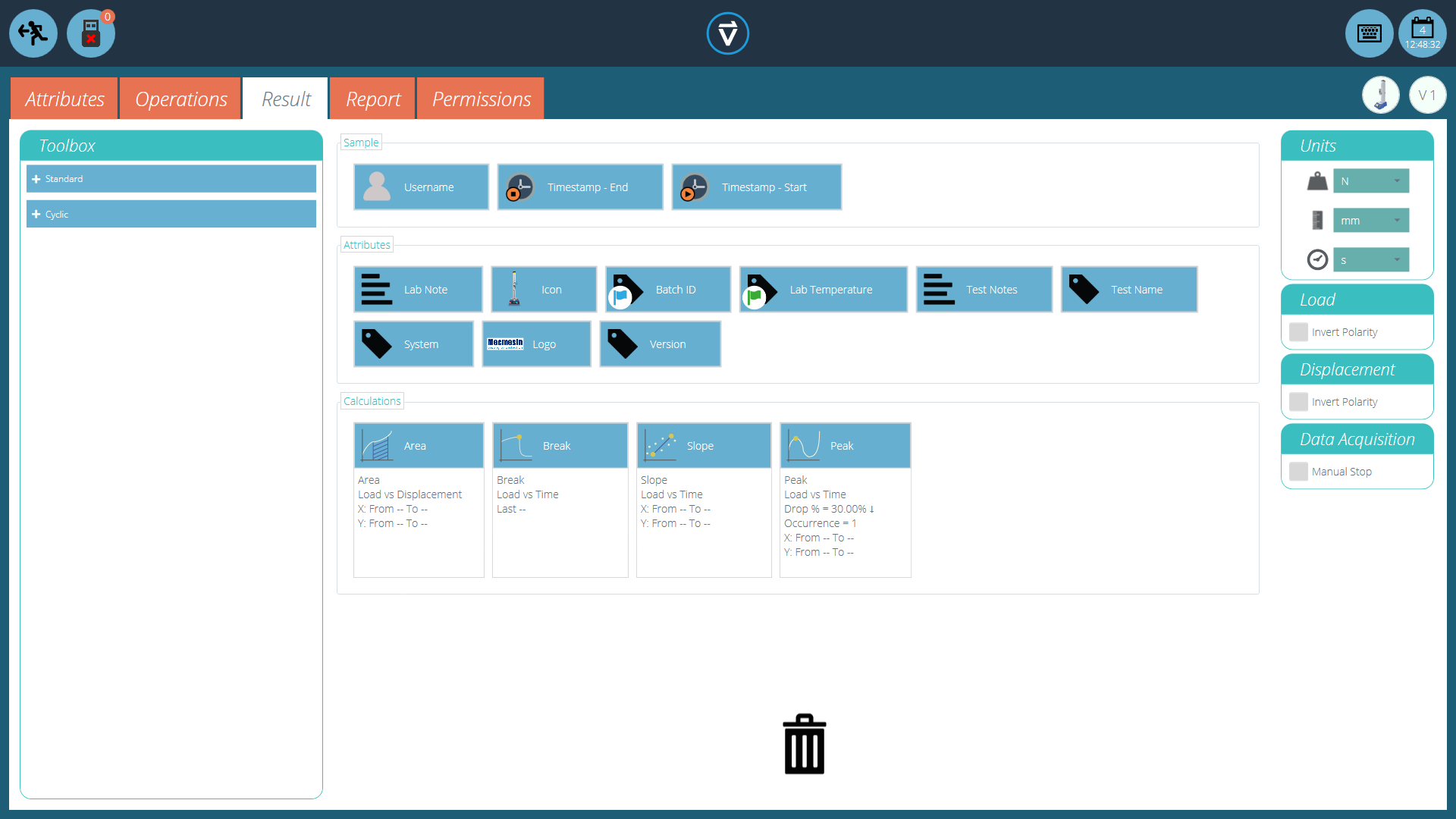
The ‘Result’ tab is where calculations used for data analysis and reporting are added. The Toolbox area contains all the elements for producing results from test data. This window allows for calculation configuration as well as adjustment of unit display settings.
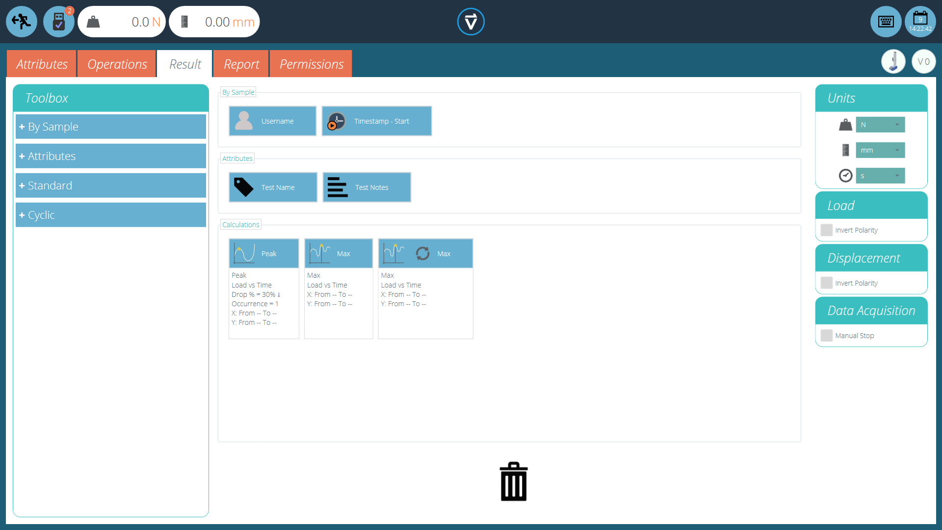
The result screen prior to setting any calculations
Details of the elements that exist within the result screen are explained below. Some elements are application-specific.
6.1 By Sample
These elements relate to the specimen and test setup, useful for tracking test details and system setup for example. Elements added here will be added to the report table. The elements include:
- Username: Adds the ‘Username’ of the person who undertook the test to the results screen,
- Timestamp start/end: Adds a timestamp for the start/end of the test to the results screen.
6.2 Attributes
These are the attributes attached to the specific test as configured earlier within the ‘Attribute’ tab. Elements added here are then available to add to reports. If an attribute within a test is not added to the ‘Result’ window, it will not available to add to a report.
6.3 Standard Calculations
Standard calculations are based on the entire timeline and all data features. In all cases, name, axes, decimal place display, range and verify may be added:
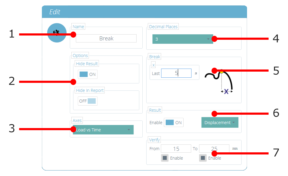
| 1 | Name: Edit the display name for the calculation |
|---|---|
| 2 | Option: Select if the Result is to be hidden in the 'results' and 'report' sections |
| 3 | Axes: Select the axes for the calculation |
| 4 | Decimal Places: Configurable from 1 to 9 |
| 5 | Range (Break): Define the boundaries for a calculation |
| 6 | Result: Used to give an alternate result at the calculated point. For example, this calculation has been setup to find break using ‘Load vs Time’ but will give the ‘Result’ as ‘Strain’ |
| 7 | Verify: Enable to set a Pass/Fail boundaries for the calculation |
Peak and Trough calculations also include:
Drop/Rise As a % of peak/trough value
Occurrence Peaks or troughs by time sequence
Order Peaks or troughs by magnitude sequence (greatest = order 1)
|
Calculation |
Function |
|---|---|
|
|
The area under a curve. When load vs displacement, this represents energy or work done. With stress vs strain, this is equal to the toughness of the material or modulus of resilience (If calculation boundaries limit calculation to the elastic region). |
|
|
Trendline: the gradient of a straight line of best fit through all the data points within an x-range, and the y-intercept of this line. |
|
|
The gradient of a straight line between two entered x or y values on selected domains. |
|
|
Mean (sum of all data values divided by the number of point values) |
|
|
The Break calculation returns the maximum load or displacement within a defined range before the end of a test. See below for more explanation. |
|
|
Peaks are defined by percentage drop after rising in y value. Here, select which peak by time sequence. |
|
|
The total number of peaks, this is defined by percentage drop and x/y range settings. |
|
|
The average value for all peaks within the defined boundaries. This is defined by percentage drop and x/y range settings. |
|
|
Troughs are defined by percentage rise after falling in y value. Here, select which trough by time sequence. |
|
|
The total number of troughs, this is defined by percentage rise and x/y range settings. |
|
|
The average value for all troughs within the defined boundaries. This is defined by percentage drop and x/y range settings. |
|
|
The value of 'y' axis for a specified value of 'x' axis or, the value of 'x' axis for a specified value of 'y' axis |
|
|
Peaks are defined by percentage drop after rising in y value. Here, select which peak by magnitude order. |
|
|
Troughs are defined by percentage rise after falling in y value. Here, select which trough by magnitude order. |
|
|
Maximum y-axis value within a range on the x-axis. |
|
|
Minimum y-axis value within a range on the x-axis. |
|
|
Percentage break, as defined using drop percentage. |
|
|
X-Intercept value at the percentage break calculated point, as defined using drop percentage. |
6.4 Break Definition
The Break calculation is an assessment of the rate of loss of load. A specimen may exhibit a peak or trough value before a break event, whereas a break is an ultimate failure to sustain sufficient load.
The range of time or displacement to be examined can be adjusted, this is entered into the ‘Break’ section. This value determines how far before the end of the test is analysed for the break value calculation.
6.5 Cyclic Calculations
Cyclic calculations operate in exactly the same way, but allow the additional selection of a specific cycle within the test to calculate the result.
When configuring a cyclic calculation simply select the desired cycle using the field at the bottom of the edit window (pictured below):

6.6 Verification of Calculations

Within the calculation ‘Edit’ window it is also possible to set up verification ranges that can be used to validate whether the data is above, below or within a specified range. Details on how to view verify whether a result is within the verification boundaries can be found in the 'Viewing Results: Calculations Display' section located in the VectorPro - All Tests Viewer and Results Viewer User Manual.
6.7 Sequence of Calculations
Calculation results are ordered on screen and in reports, as defined here. Calculations on the far left will be at the top of the ‘Results’ screen and calculations on the right will be at the bottom, bear this in mind when setting attributes on the ‘Result’ editor screen.
6.8 Units and Polarity
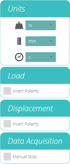 |
Calculation results are ordered on screen and in reports, as defined here. Calculations on the far left will be at the top of the ‘Results’ screen and calculations on the right will be at the bottom, bear this in mind when setting attributes on the ‘Result’ editor screen.
|
7 Report
The screenshots illustrated in this section are using a MultiTest-dV and show the features available to this test stand.
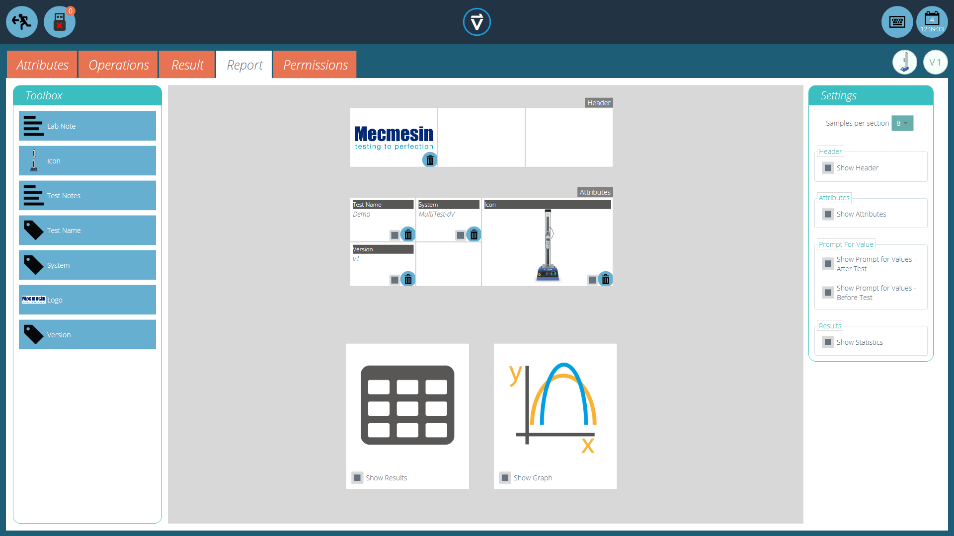
The report Toolbox is populated with attributes added within the ‘Result’ window.
Simply drag-and-drop elements into the predefined areas on the report screen to select those required to appear in the PDF and printed reports.
| To view and export the completed report simply navigate to the ‘Results’ page for the desired test and click the ‘Report’ button (Pictured left). |
For more information regarding exporting reports and data, see the VectorPro - Running a Test, Reporting and Exporting User Manual.
Preparing the report layouts has three main stages:
- Populate the report toolbox,
- Populate the report template,
- Position the elements and configure reporting options.
7.1 Populating the Report Toolbox
 A report can include any attribute attached to a test. The default attributes available in any test are:
- Test name (the same for all versions),
- Test description (can vary by version),
- System (test system or instrument used).
These can be supplemented by any other custom attributes (image, label and note). Tables of results and graphs are available by default in every report.
The image above shows an example scenario where the user has added nine ‘Attributes’ to their ‘Result’ screen, these will now be available on the ‘Report’ designer screen.
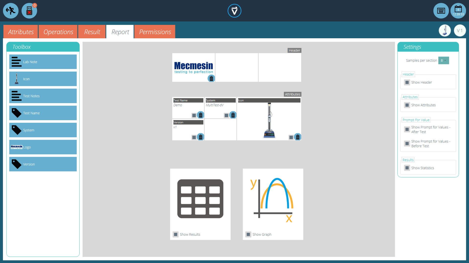 To populate the ‘Report’ follow the steps below:
- Begin in the ‘Result’ tab within the ‘Test Designer’ screen. Then simply drag-and-drop attributes or calculations into the main screen. Attributes and calculations have to be placed within their corresponding section on the main screen.
- Go to the ‘Report’ tab, to find the selected attributes in the ‘Toolbox’, next to a blank page.
- Drag attributes onto the blank page into the desired position. These can be refined, alongside graph and results table at the next stage. For ‘Report’ configuration see the next page.
7.2 Report Configuration
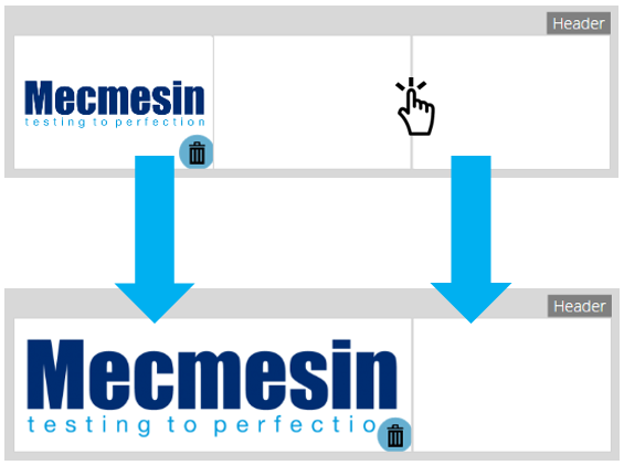
Dividers (highlighted below) can be removed or added by clicking them and attributes can be deleted by selecting the ‘Trash’ icon at the bottom of each attribute.
Below these elements, the report will display a table of all selected samples, followed by a graph of up to eight samples (The number of displayed samples can be changed in the right-hand plane).
Additional samples appear on subsequent pages in sets of user-defined samples.
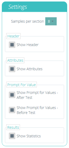 |
Located on the right-hand side of the screen is the report ‘Settings’ menu. From here the user has the ability to change several other elements, such as:
|
Selecting ‘Show Prompt for Values’ enables these attributes to be exported via Email, Excel and PDF.
| To view and export the completed report simply navigate to the ‘Results’ page for the desired test and click the ‘Report’ button (Pictured left). |
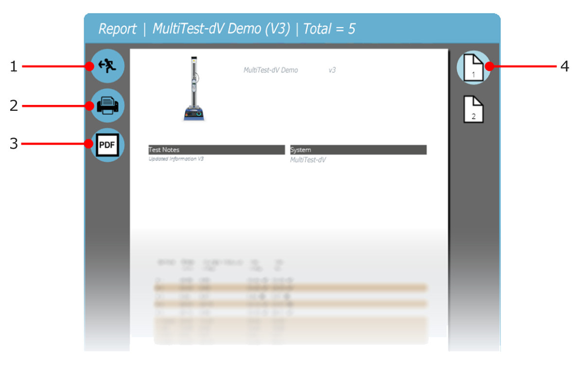
| 1 | Exit |
|---|---|
| 2 | Print Report |
| 3 | Save as PDF |
| 4 | Go to page number shown |
Reports are laid out with user-placed elements on page 1, followed by tabulated results and a graph. Up to eight samples are shown per page, up to a further eight on the next page and so on. Statistical results are shown below the final table.
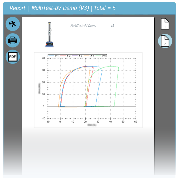
By default PDF reports are saved to C:\ProgramData\Mecmesin\VectorPro\reports
8 Permissions
The test ‘Permissions’ tab works in the same manner as the main ‘Permissions’ control in VectorPro. Simply drag users into the cards to grant permissions to: save test copies and edits, execute the test, view the report, print (export) reports or delete samples.
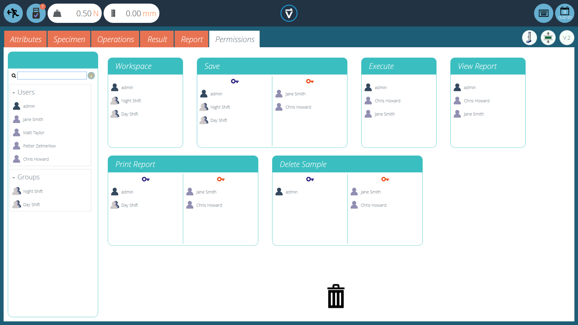
In the example above, ‘Jane Smith’ and ‘Chris Howard’ can manage all aspects of this test, whereas the group ‘Night Shift’ has limited permissions. To remove a user from a card simply drop them into the trash located at the bottom of the screen.
It is important to ensure that if a user is required to execute a test that they have access to both ‘Execute’ and ‘Workspace’ permissions as well as access to the test system being used, this is configured in the main ‘Permissions’ screen. For more information relating to verification boundaries please refer to the 'Attributes Permission screen interface' section located in the VectorPro - Workspace and User Management User Manual.
The ‘Workspace’ permission places a tile for the test being edited in the user’s workspace, by default this is always created for the user who created the test. It is possible for a user to access tests without having the ‘Workspace’ permission by using attribute permissions. This is fully explained in section 'Grouping Attributes - Creating Test Folders'.
A user with permission to access the ‘All Tests’ viewer can also see a list of all tests and subsequent versions of each test but, is only able to use tests and versions for which they have permission.
8.1 Prompt for Authorisation Settings
For certain functions, such as saving a test and deleting samples, it is possible to assign a user the ability to carry out the function only with direct action from another user with ‘authorisation’ rights.
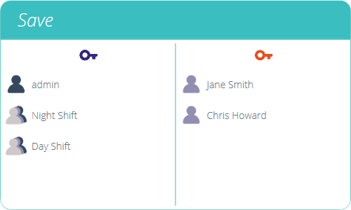
To do this place the user on the left-hand side of the permissions card, shown above. Users on this side of the card require permission to carry out the designated function, expect ‘admin’.
Users on the right-hand side ‘authoriser’ section of the card have the ability to carry out the function (in this case saving the test) and they also have the ability to grant authority to users on the left-hand side to carry out this function.
In the example above, 'Jane Smith' and 'Chris Howard' have permission to save without authorisation and can authorise the action of other users. Users in the 'Night Shift' and 'Day Shift' groups can only save with authorisation from users on the right.
If a user contained within the ‘Day Shift’, for example, attempts to save a test they will be presented with the ‘Prompt for Authorisation’ sign off window shown in the next section.
8.2 Prompt for Authorisation Sign Off
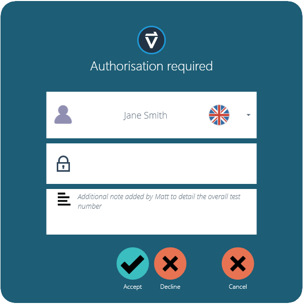
When a user who requires authorisation carries out a function the following pop-up will appear on the screen. Here there are three entry fields:
- Authoriser: The top drop-down section allows selection of the desired authorisation account,
- Password: The middle section is where the selected user enters their login password,
- Authorisation note: This is where the authoriser can enter a note detailing what action has been taken. It is required that accept or decline are selected for this note to be saved.
At the bottom of the screen, the user is presented with three actions. These allow the user to:
- Accept the change made and save the note to the event log,
- Decline the change made and save the note to the event log,
- Cancel the change, the note will not be saved but all actions are still logged in the event log.
The note entry saved can be viewed in full in the event log along with the details relating to the change such as the user who asked for authorisation. The user who authorised the change, the time and date or the event and what was changed.
9 Saving a Test
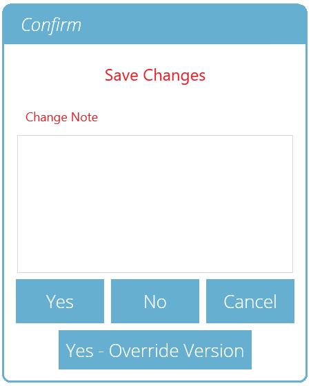
When the Test Design function is exited, the screen presents a pop-up box pictured below and asks if save changes are required. The ‘Yes’ command saves the test and increments the version number.
There are certain factors to be aware of when saving a test:
- If a test name is changed, it only applies to the latest version of that test. Previous versions remain linked to this test, but the previous version’s test name will be shown when viewing versioning history.
- When an attribute or calculation is added or removed, or test parameters changed, these are not applied to previous versions of the test.
- The test version that is edited becomes the new version (e.g. a test reaches version 5, and version 3 is then edited – this edit becomes version 6 and changes added to versions 4 and 5 are therefore not included).
9.1 Override Test Version
Within VectorPro, it is possible to override a version of the test when saving it, rather than having to increment the test version.
When exiting a test, which is being edited, the pop-up box pictured above appears, the ‘Yes – Override Version’ option allows saving of any changes made, without incrementing the version number.
This feature is useful if the changes are minor or if the user is developing a test method.
Permission to allow test versions to be overridden may be configured. To do this simply drag-and-drop users into the override version card in the general permissions screen. This enables the ability to override test files, or remove them from the card to take away their permission. This is useful for protecting tests from being changed without incrementing the version.
9.2 Adding Change Notes to Saved Tests
In addition to the override feature, there is also a ‘Change Note’ field within the save confirmation window. The change note field is an area where text entry detailing the alterations that have been made.
This is saved with the test and can be viewed in the ‘All Tests’ window and ‘Test Results’ screen as well as being stored in the event log. Change notes are only saved when clicking either ‘Yes’ or ‘Yes – Override Version’. Please note there is a 300-character limit.
To view change notes on the ‘Test Results’ screen, simply click the arrow icon (Circled) to expand the field and display the change note for the selected test version.
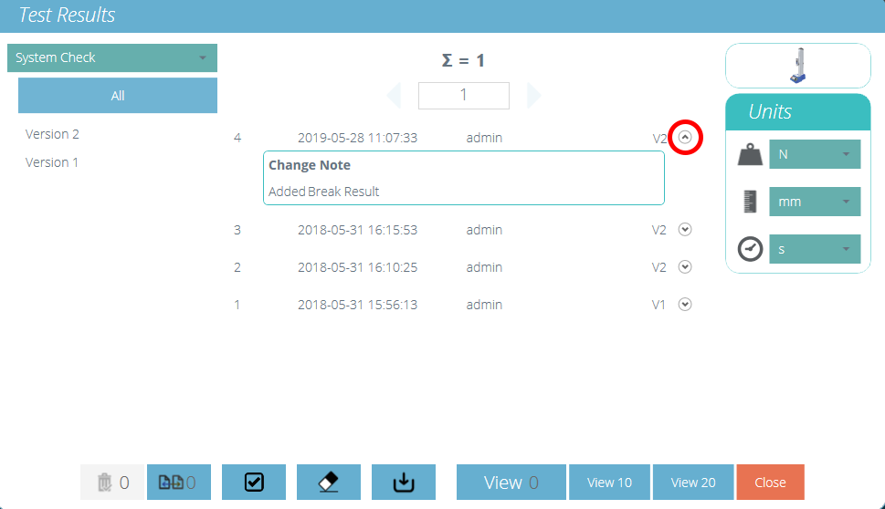
‘Test Results’ viewer showing the change note for the latest test revision.
10 Further Information
For more information relating to VectorPro, please return to the User Guidance section of this user manual and continue to the next applicable user manual.


