1 Designing a Test (VectorPro MT Version)

 |
431-955 February 2020 |
2 Introduction
VectorPro™, VectorPro™ MT and VectorPro™ Lite are all registered trademarks of Mecmesin Ltd.
VectorPro is a dedicated software solution used for the programming and acquisition of data from a range of Mecmesin test stands and instruments.
2.1 User Guidance
This user manual section covers designing a test for VectorPro MT compatible instruments only, for further guidance relating to other aspects of VectorPro please refer to one of the documents listed below.
2.1.1 VectorPro™ User Manuals
Click one of the links below to navigate to the applicable user manual.
 |
 |
 |
Designing a Test MT Version (Current Document) A detailed guide to designing a test for VectorPro MT compliant test systems. |
|
Covers designing a test for VectorPro Lite compliant test stands and devices |
 |
 |
All Tests Viewer and Results Viewer A guide explaining the functionality of the All Tests Viewer and Results Viewer. |
 |
 |
|
View the latest version of the Mecmesin VectorPro Software License Agreement. |
 |
- 1 Designing a Test (VectorPro MT Version)
- 2 Introduction
- 3 Getting Started
- 4 Attributes
- 5 Specimen
- 6 Operations
- 6.1 Operation Definitions
- 6.1.1 Common
- 6.1.2 Load Rate Operations
- 6.1.3 Relative
- 6.1.4 Target
- 6.1.5 Pause
- 6.1.6 Pause Operation
- 6.1.7 Remove Extensometer (Pause Operation)
- 6.1.8 Important Information
- 6.1.9 Enter Grip Separation (Pause Operation)
- 6.1.10 Example Grip Separation Test – Without Extensometer
- 6.1.11 Example Grip Separation Test – With Extensometer
- 6.2 Toe Correction Operation
- 6.3 Vector Cloud Solutions
- 6.4 Creating a Test Sequence
- 6.5 Editing an Operation's Settings
- 6.6 Test Acquisition Settings
- 6.1 Operation Definitions
- 7 Result
- 7.1 By Sample
- 7.2 Attributes
- 7.3 Standard Calculations
- 7.4 Calculations Available
- 7.5 Value at Operation Result
- 7.6 Break Definition
- 7.7 Specimen Calculations
- 7.8 Young’s Modulus Calculation Settings
- 7.9 Young’s Modulus Calculation Method
- 7.10 ISO 6892 Ae – (Percentage Yield Point Extension) Result Calculation
- 7.11 Verification of Calculations
- 7.12 Formula
- 7.13 Building a Formula Result
- 7.14 Example Calculation
- 7.15 Hide Result & Hide in Report Functions
- 7.16 Sequence of Calculations
- 7.17 Units and Polarity
- 8 Report
- 9 Permissions
- 10 Saving a Test
- 11 Further Information
3 Getting Started

3.1 Test Names and Versions
Click the ‘New Test’ tile to configure a new test. The ‘New Test’ screen, pictured above, is displayed onscreen. VectorPro MT test stands are listed under the OmniTest tab. Within this tab select the desired test system or model.

The ‘New Test’ selection screen, select which instrument is used.
The screen shown below will be displayed, enabling the selection of Tension, Compression, or 3-Point bend test modes. Press 'OK' to continue.

The ‘New Test’ selection screen, select which test type you are using.

A new test contains a series of settings tabs; Attribute configuration, Specimen definition, a sequential Operations, Result calculations, an optional editable Report layout and Permissions specific to this test.
4 Attributes
Attributes extend the information about a test. Some are reserved by default and others are customisable. The ‘System’ attribute, for example, is not editable and is available in results and reports to indicate the test system used for the test. When a new test is first created, two attributes are automatically added. ‘Test Name’ entered from the new test screen and a blank ‘Test Notes’ attribute.
Attributes can be added to store notes, labels or attach images to the test. Attributes can be configured to prompt for input value before or after the test.

Icons for a ‘Label’, ‘Note’ and an ‘Image’ attribute.
4.1 Test Name
Default attribute
Names the test routine and all versions. This attribute can be edited but is in all versions of the test, not just subsequent versions.
4.2 Test Notes
Default attribute
Applies to this test version, and is inherited by subsequent versions until amended again.
4.3 Add New and Existing Custom Attributes
Once an attribute has been used in VectorPro, it is incorporated into the database and becomes available to all tests under the existing attribute section. An attribute must have a unique name and can be a ‘label’ (up to 30 characters), a ‘note’ (up to 300 characters) or an 'image'.

Icons for a ‘Label’, ‘Note’ and an ‘Image’ attribute.
Image attributes allow the insertion of an image file, which may be browsed for, or captured on a webcam. The first image to be assigned appears as the ‘Workspace’ icon for this test (attributes for a test, once assigned, cannot be rearranged).
Image and note attributes also have a ‘Prompt for Value’ setting. Options available are:
- None: No action is prompted before or after the test, fixed image or note can be entered here,
- Before Test: The user is prompted for an image file or note before the test,
- After Test: The user is prompted for an image file or note after the test,
4.4 Prompt for Value Feature
Within VectorPro, attributes can be configured to prompt for input value before or after the test is run.
This can be applied to a note, label or image attribute which enables the test to prompt the user for input before or after testing. These labels are then saved to the relevant result file. This is shown below whereby a ‘Batch ID’ label has been set up with a before test prompt and a ‘Lab Temperature’ label has been set up with an after test prompt.
In the example screenshot below when editing or creating a test, the image and note attributes have the option to configure ‘before’ or ‘after’ test options. For example, this can be useful for logging important notes or for adding pictures of the specimen pre-test and post-test.

This image shows the ‘prompt for’ settings highlighted by the red circle.
4.4.1 Prompt for Value – Flag Definitions
Prompt for Value attributes carry flag markers to give easy visual identification to whether they are before or after the test values. These markers are visible in the ‘Results’ tab when both within the ‘Test Designer’ and the ‘Results Viewer’.

A diagram displaying the new flag markers. The left-hand icons are the markers within the ‘Results’ design page and the right hand are within the ‘Results Viewer'. Before test flags are highlighted in blue and after test flags are highlighted in green.
4.4.2 Prompt for Value - Predefined List
Label attributes using the ‘Prompt for Value’ feature can be set up with a predefined list. For example, these lists could be used to state batch numbers or the colours of the test specimens.
To use the predefined list feature the user must first create a new label attribute, then select the ‘Predefined List of Values’ option to display the input table. Enter the values by pressing ‘Add’ and remove unwanted values by pressing ‘Remove’.

In the example shown both above and below a label attribute called ‘Batch Number’ is configured within the test designer with ‘Before Test’ selected and a predefined list of batch numbers entered.

Upon starting the test, the ‘Prompt for Value – Before Test’ window appears. Entry input is available, for any attributes that have been configured to prompt before the test is run.
4.5 Grouping Attributes - Creating Test Folders

Grouped attribute tile.
Within VectorPro it is possible to assign the same attribute to several tests so it can be used as a filter to group tests together on the main ‘Workspace’ screen.
This allows for easy grouping of tests based on a common image, note or label. These tests are then grouped into a brown tile like the one pictured above. The following pages detail how to achieve this.

Within the relevant test, place the desired attribute. For example, in the screen above an attribute called ‘Lab Notes’ is being used by the operator to describe the test being executed. Previously used attributes can be found in the ‘Existing Attributes’ section (highlighted in red).

Editing the attribute permissions.
Next, exit the test being edited and click on the ‘Permissions Tile’ located on the far left of the home ‘Workspace’. From here drag-and-drop the relevant user into the specified attribute tile (See the image above).
Attribute tiles are located at the bottom of the ‘Permissions’ screen, below the test system tiles. Use the filter toolbar to show only attributes. In this example above, ‘admin’ has been given rights to see all tests using the ‘Lab Notes’ attribute.

Now the attribute group is present in the home ‘Workspace’ for the admin user to see. For users running a large number of projects, test definitions can be organised into groups only, removing individual test tiles. Therefore helping to organise the screen to maximise the efficiency of the ‘Workspace’.

To achieve this, click edit on the test required to be made invisible, then navigate to the permissions tab and remove the relevant user from the ‘Workspace’ attribute. In this case, as the admin wishes to hide the test, this user is removed from the ‘Workspace’ tile by simply dragging and dropping the user into the trash, as pictured above.
In the second image below, the test files are only visible within the ‘Lab Notes’ attribute group. In this scenario, the workspace rights for admin have been removed from all test files but as the tests contain the ‘Lab Notes’ attribute (which admin has permission for) the tests appear as an organised folder instead of individual tiles.

Two workspaces using the same database, the lower has used permissions grouping for each individual test to create a subfolder with all the tests in.
4.6 Searching Within Attribute Groups
Within VectorPro the user can search within the created ‘Attribute Groups’. To access this feature click on a brown group tile that is either linked by a note or label attribute to open the window pictured below (search is unavailable on groups linked by image attributes).
Here, all the tests which contain the ‘Lab Notes’ attribute can be seen. The user can then search using the bar at the top of the window as well as using filters for prompt for value settings (None/Before Test/After Test). When entering a search term the user is presented with three additional options for narrowing the search:
- Both: Search both the attribute value and the test name.
- Attribute Value: Search only the value entered into the attribute.
- Test Name: Search only the name of the test which contains the selected attribute.

Once a test attribute value is selected, the user is presented with the following options at the bottom of the window:
- All: Will show the selected attributes test within the ‘All Tests’ viewer. This is to explore the test settings, operations, results and versioning.
- Results: Displays the selected attributes test within the ‘Results’ viewer. Users can view and delete the test results here as well as being able to compare different tests and versions.
- Edit: This opens the selected test in the test designer screen.
- Execute: Clicking ‘Execute’ loads the operation sequence to the test system and opens the test display screen.
- Close: Closes the window.
5 Specimen
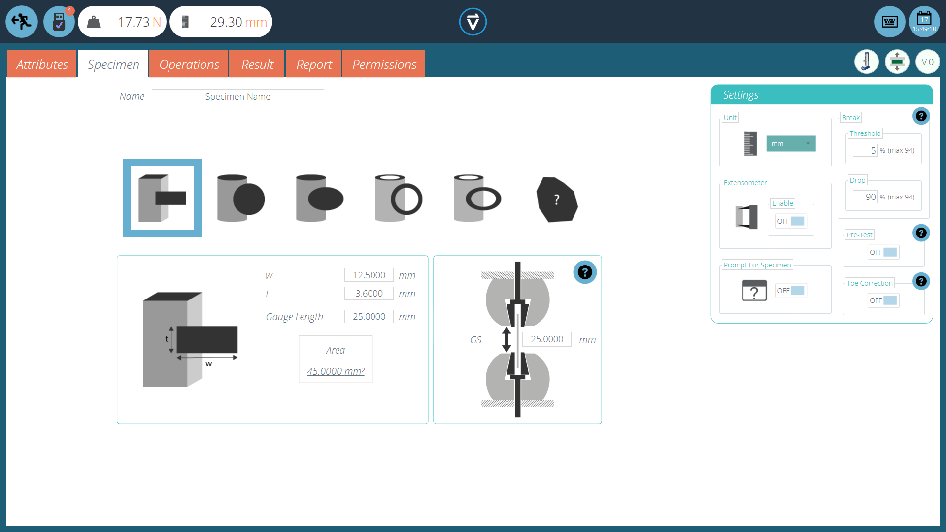
The ‘'Specimen’ screen is used to define physical dimensions of the specimen, configure the extensometer and configure break settings.
The ‘Specimen’ screen is where specimen geometry and dimensions can be defined. These physical dimensions are used to derive stress and strain calculations.
Other options within this screen, allow the user to:
- Name the specimen being used
- Select whether or not an extensometer is being used and which type (Anlogue or Digital)
- Define the displacement units
- Set ‘Pre-Test’ preload (load a sample before a test timeline operation sequence is commenced
- Configure break detection
- Toggle whether to ‘Prompt for Specimen’ value before starting the test
- Specify if the 'Toe Correction' setting is enabled.
Enabling ‘Prompt for Specimen’ presents the screen pictured below before the test starts. Here the user can measure and enter individual dimensions for the specimen under test.

The extensometer settings are displayed in the top right of the prompt for specimen window.
5.1 Specimen Shape Definitions
There are eight distinct shapes that can be selected to define the specimens dimensioning, below is a visual guide to explain these.
|
Icon |
Shape Definition |
|---|---|
 |
This is for setting the dimensions of quadrilateral specimens. Set the Width (w) and Thickness (t) of the specimen, as well as the gauge length. |
 |
This is for setting the dimensions of circular specimens. Set the diameter (d) and the gauge length. |
 |
This is for setting the dimensions of elliptical specimens. Enter parameters (a), (b) and the gauge length to define the specimen. |
 |
This is for setting the dimensions of hollow circular specimens. Set the internal (d0) and external diameter (d1) as well as the gauge length to define the specimen. |
 |
This is for setting the dimensions of hollow elliptical specimens. Set the internal and external dimensions as well as the gauge length to define the specimen. |
 |
This is for setting the dimensions of custom specimens. Set the cross-sectional area and the gauge length of the shape. |
 |
This is for setting the dimensions of quadrilateral specimens in a 3-point bend test. Set the width (b) and height of the specimen (h), as well as the length of the specimen between the supports (l). |
 |
This is for setting the dimensions of circular specimens in a 3-point bend test. Set the diameter of the specimen (d) and the length of the specimen between the supports (l). |
5.2 Configuring an Extensometer
|
OmniTest and MultiTest-dV(u) test systems can use Mecmesin external extensometer devices such as the LTE-700, 1000 or 1200. These enable accurate measurement of specimen strain performance directly on the specimen between two contact points. This is crucial for calculating Young's modulus (MOE) or strain until a yield point. To use an extensometer with either an OmniTest or MultiTest-dV(u) test system, plug the Mecmesin extensometer into the test system and then switch the ‘Extensometer’ switch to ‘ON’. For LTE-700, 1000 and 1200 (Long Travel Extensometer) devices, use ‘Enable’ extensometer only. For Mecmesin supplied short axial contacting extensometer/deflectometer select ‘Enable’ and ‘Analogue’. Within the ‘Settings’ panel, the user can select the units used when entering the specimen dimensions. |
 |
5.3 Configuring Break Settings
|
Break settings for the test can be configured on the right-hand settings panel. These options enable configuration of the settings to determine when a break condition is detected:
For example, if set to 5% on a 1000N load cell the load reading would have to be above 50N for a break condition to be detected.
For example, if set to 90% a specimen pulled to 100N would need to exhibit a sharp drop from 100N to 10N for a break condition to be detected. See section 'Break Definition' for information concerning break calculations |
 |
5.4 Configuring Pre-test Preload
|
Pre-test preload allows the application of a specified force to the specimen prior to commencing the main operation sequence. The available settings are ‘On/Off’ and the desired load value |
 |
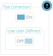
5.5 Configuring Toe Correction
|
'Toe Correction' is a post-test method of compensating a specimen that experiences the effects of 'slack' at the beginning of a test. Slack is defined as any artifact caused by seating or alignment of a specimen, when first loaded. This is not related to any characterisic or property belonging to specimen itself. Some test standards such as ASTM refer to this as 'Toe Region'. Others define use of toe correction to determine a 'zero-deformation point' from which calculations or results are referenced. The correction is sympathetic to the samples mechanical properties and is calculated from the specimen's stiffness (Stress vs Strain). The available settings are ‘On/Off’ and 'Use User Defined'. Use User Definded = Off: Toe correction applied automatically Use User Defined = On: User defined manual Toe correction post-test See Toe Correction operation for more details. XXXXX |
 |
5.6 Grip Separation
Grip separation is used in VectorPro to derive strain when an extensometer device isn’t connected. This also includes tests where the extensometer is being removed before the end of the test.
Within the specimen screen the ‘Gauge Length’ field is used to populate the grip separation for the start of the test. This value is used to measure strain derived from the internal machine displacement.
In tests where an extensometer is being used the following is true (Also applies when the extensometer is being fitted during the test):
- The gauge length field should be populated with the gauge length of the extensometer.

In the example above an extensometer with a gauge length of 50 mm is being used.
In tests where grip separation is being used from the start of the test the following is true:
- The gauge length field should be populated with the starting grip separation, with the test sample loaded.

In the example above grip separation is being used to derive strain. The starting separation is 65.72 mm.
5.6.1 Notation - Nominal Strain
When an extensometer cannot be used, or it is required that it be removed after a specimen has yielded, there is provision (in certain test standards) to use the machine displacement as the strain source.
For example, ISO 527-1 Tensile Plastics test standard recommends the use of an extensometer until specimen yield and then removal of the device. Subsequent strain readings are then sourced from the machine’s internal displacement. This method produces “Nominal Strain”. This is advantageous if the gauge length of the extensometer does not cover the expected elongation range of the specimen, or if a sample necking region occurs outside of the fixed gauge length.
To incorporate this type of strain measurement, VectorPro allows the use of a specimen entry called “Grip Separation”. This is the distance between the contact face of the opposing jaw faces in each grip and is usually measured manually following a pre-stress or load to the specimen.
Grip Separation is either used to calculate all strain measurements if no extensometer is used or it is used in combination with extensometer strain readings (based on the device’s gauge length) recorded to an agreed point (usually just beyond a yield). This is followed by a pause and removal of the extensometer. Strain from this point is based upon the grip separation entered.
The combined strain results following removal of an extensometer are “Nominal Strain” values.
5.6.2 Configuring a Test
For example test configurations, please refer to the following section 'Enter Grip Separation'.
6 Operations
6.1 Operation Definitions
The ‘Operations’ screen allows the definition and configuration of physical stages that are completed during the test. The system works using drag-and-drop actions, to move operations from the left-hand side panel into the timeline. These commands can be edited to enable a vast array of test methods.
Within the operations there are four main categories, these are Common, Relative, Target and Pause.
6.1.1 Common
These are operations that are not dependent on crosshead position or test type and function the same in all tests.
|
Icon |
Action |
Settings |
|---|---|---|
|
|
Appy a pre-load to the specimen in tension.
|
|
|
|
Apply a pre-load to the specimen in compression. |
|
|
|
Move the crosshead back to the start position or set home position. |
|
|
|
Tare the load value. |
|
|
|
Tare the displacement value from both the ballscrew and tacho encoders, plus the extensometer or deflectometer |
|
|
|
Tare the extensometer value only. |
|
|
|
Tare all values. (Load, displacements and extensometer value). |
|
|
|
Pull the specimen at a constant speed until a break condition is detected. |
|
|
|
Apply a compressive force to the specimen at a constant speed until a break condition is detected. |
|
|
|
Apply a flexural compressive force to the specimen at a constant speed until a break condition is detected. |
|
|
|
Pull the specimen at a constant load rate until a break condition is detected. |
|
|
|
Apply a compressive force to the specimen at a constant load rate until a break condition is detected. |
|


6.1.2 Load Rate Operations
6.1.3 Relative
These are operations that are based on current channel values. For example, if the crosshead is at 40mm displacement and an operation to move up 10mm is run, the final position is 50mm.
|
Icon |
Action |
Settings |
|
|---|---|---|---|
|
|
Move the crosshead down at a constant speed, with optional hold time.
|
|
|
|
|
Move the crosshead up at a constant speed, with optional hold time. |
|
|
|
|
Increase the load on the specimen at a constant speed, with optional hold time. |
|
|
|
|
Decrease the load on the specimen at a constant speed, with optional hold time. |
|
|


6.1.4 Target
These are operations that are based on the last tared (zero) channel values. For example, if the system is at 150mm displacement a target of 100mm is run, the system will move down 50mm to place the crosshead 100mm from the last tared zero.
|
Icon |
Action |
Settings |
|---|---|---|
|
|
Move to a load value at a constant speed, with optional hold time. |
|
|
|
Move to a crosshead position at a constant speed, with optional hold time. |
|
|
|
Move to a strain value at a constant speed, with optional hold time. |
|
|
|
Move to a stress value at a constant speed, with optional hold time. |
|
 |
Move to a target load at a constant load rate, with optional hold time. |
|


6.1.5 Pause
These operations pause the test. For example, a pause operation can be used to allow extensometry devices to be fitted after preloading or to remove an extensometer before a specimen breaks, preventing the equipment from becoming damaged.
|
Icon |
Action |
Settings |
|
|---|---|---|---|
|
|
Pause the test and display a user-defined message. |
|
|
|
|
Pause the test to allow the extensometer to be removed, by default the displacement source is then swapped to the test stand encoder. |
|
|
|
|
Pause the test to enter grip the separation. |
|
|


6.1.6 Pause Operation

The pause operation in VectorPro stops the test stands movement and display a popup text message when the operation is reached in the test timeline. The text displayed can be set by editing the operation settings in the test timeline. In the example above the message prompts the user to fit an extensometer. To continue the test the user must press the play button on the front panel of the test stand.
6.1.7 Remove Extensometer (Pause Operation)

This operation allows the extensometer to be removed during the test, before a break condition. This is crucial if the elongation range of the specimen is higher than the device’s measurement range, for a test method requirement, or for the preservation of extensometers when high energy break test specimens are measured.
In a typical situation, the specimen is pulled to just past the linear section of its elastic region or to a point where an offset yield can be measured, before removing the extensometer.
The text displayed can be customised by editing the operation’s individual settings in the test timeline. In the example above the default message is used, this prompts the user to remove the extensometer.
To continue the test the user must press the play button displayed on the front panel of the test stand.
6.1.8 Important Information
Upon removing the extensometer strain measurement for the test is swapped to use the test stand encoder.
Please note that as the test stops the specimen can ‘relax’ this will cause a visible drop on the graph (see the circled image below).

For more information relating to configuring a test that allows an extensometer to be removed please see the following section 'Example Grip Separation Test - With Extensometer'.
6.1.9 Enter Grip Separation (Pause Operation)

This operation is designed for tests where an extensometer is not being used or is being removed during the test. It allows the current grip separation to be entered. In most applications, this operation is used after the sample has been pre-loaded.
The next sections cover how to use grip separation with and without an extensometer, it is recommended to read the VectorPro - Running a Test, Reporting and Exporting User Manual.
6.1.10 Example Grip Separation Test – Without Extensometer

When deriving strain from grip separation in a test with no extensometer fitted, it is important to first enter the distance between the upper and lower grip face into the section labelled ‘Gauge Length’, as shown in the image above. This is found under the ‘Specimen’ tab, see section 'Specimen'. The value entered here automatically populates the grip separation section, labelled ‘GS’, with the same value. This distance could be measured before a test-run or with the sample fitted following a suitable preload.
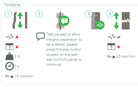
Next, navigate to the ‘Operations’ tab and configure a suitable preload stage for the test sample, see operation 1 above,
Immediately after the pre-load stage place an ‘Enter Grip Separation Pause’ operation’, followed by a ‘Tare Displacement’ operation, as seen in operations 2 and 3 above.
The timeline operations as followed sample pre-loaded to 5N, the test (operation 2), allowing the operator to measure and enter the grip separation. This method ensures any machine compliance (movement of grips or load cell) is minimised.
This grip separation value is then used to record the strain for the test, derived from the value entered in step 1.
In this example, the displacement channel (used to derive the specimen strain) is then tared by operation 3.
At operation 4 the sample is pulled in tension until break.
To run the test click the appropriate icon located on the workspace. Load the sample into the test stand. Next, zero the stand and set the home position with a sample loaded, see section 'Control Bar' located in the Running a Test, Reporting and Exporting User Manual for more information.
To start the test press the play button located at the top right of the screen.
After the pre-load stage, the onscreen pop-up shown in the image above appears. The grip separation should be measured and entered it into the box highlighted above, once ready press the ‘Accept’ button onscreen.
Press the 'play' button located on the front panel of the test stand to continue.
The test will run until completion. Only if it is safe to do so, press the ‘home’ button on the front panel of the test stand to return to the loading position set in step 7.
It is not a requirement to use the ‘Enter Grip Separation Pause’ for tests using grip separation as the feedback for strain. The specimen gauge length entry initially entered, will supply the required value to calculate test strain but the method above can potentially provide more accurate results.
If using the gauge length from the specimen screen as the strain source, it is crucial that the sample and grip setup has no measurable deflection errors before starting the test. The grip separation at the beginning of the test matches the value entered in the specimen tab.
6.1.11 Example Grip Separation Test – With Extensometer
For tests where grip separation is being used to derive nominal strain after an extensometer has been removed, use of both the ‘Enter Grip Separation Pause’ and ‘Remove Extensometer Pause’ operations is required.
Extensometers may be removed to protect the device when testing samples that fail with high elastic energy or fracture violently, or if the elongation range of the specimen is higher than the device’s measurement range. Below is an example showing one possible test configuration:
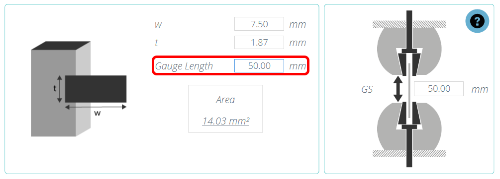
It is important that the initial gauge length of the extensometer device is entered in the ‘Specimen’ tab of the test designer, as shown in the image above.
Next, configure in the right-hand panel of the ‘Specimen’ screen whether a digital (long travel) or analogue (short travel) extensometer is being used, for more information please see section 'Configuring an Extensometer'.

Navigate to the ‘Operations’ tab and configure a suitable preload stage for the test sample. See operation 1 above.
Immediately after the pre-load stage place an ‘Enter Grip Separation Pause Operation’, followed by a ‘Tare Displacement’ operation. See Operations 2 and 3.
In this example Operation 4 is a strain target (It is also possible to use a load or displacement target). This target should be past the materials linear elastic region and offset yield and ideally, before its maximum load/stress and safely before the sample’s failure point.
Operation 5 is a ‘Remove Extensometer Pause’ operation; this enables the extensometer to be removed. Specimen strain from grip separation. The test ends with a pull to operation (Operation 6).
Next, configure any attributes, results, reports and permissions within the test designer and save the test.
Press the 'play' button located at the top right of the screen.
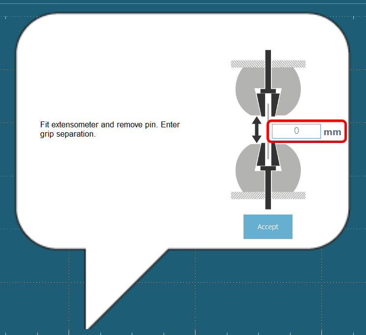
After the pre-load stage, the onscreen pop-up shown in the image above appears. The grip separation should be measured and entered it into the box highlighted above, once ready press the accept button onscreen.
At this point fit the extensometer to the sample. Once ready press the accept button onscreen.
Press the 'play' button located on the front panel of the test stand to continue.
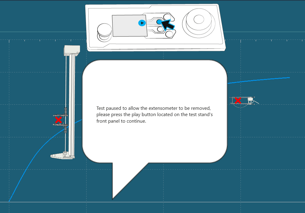
In this example from operation 4 the test runs until 3% strain is reached and pause. At this point the image above is shown, to continue safely remove the extensometer and press the play button located on the front of the test stand.
The test will then run until completion. If it is safe to do so press the home button on the front panel of the test stand to return to the loading position set in step 8.
6.1.11.1 Important Information
Upon removing the extensometer, strain measurement for the test is swapped to use the test stand internal displacement. Please note that as the test stops the specimen can ‘relax’ this will cause a visible drop in the graph (see the circled image above).
Elastic specimens will typically have a larger drop, taking longer to remove the extensometer and grips with high system deflection may also increase the size of the drop.
6.1.11.2 Further Information
For more information regarding grip separation, nominal strain and the removal of extensometer devices it is recommended to read the following section 'Grip Separation'.
6.2 Toe Correction Operation
When toe correction has been enabled in the specimen screen, the choice of 'Use User Defined' being ‘On/Off’ affects the following VectorPro operations:
6.2.1 User User Defined 'Off'
When set to 'Off' the software uses an automatic Toe Correction operation post-test.
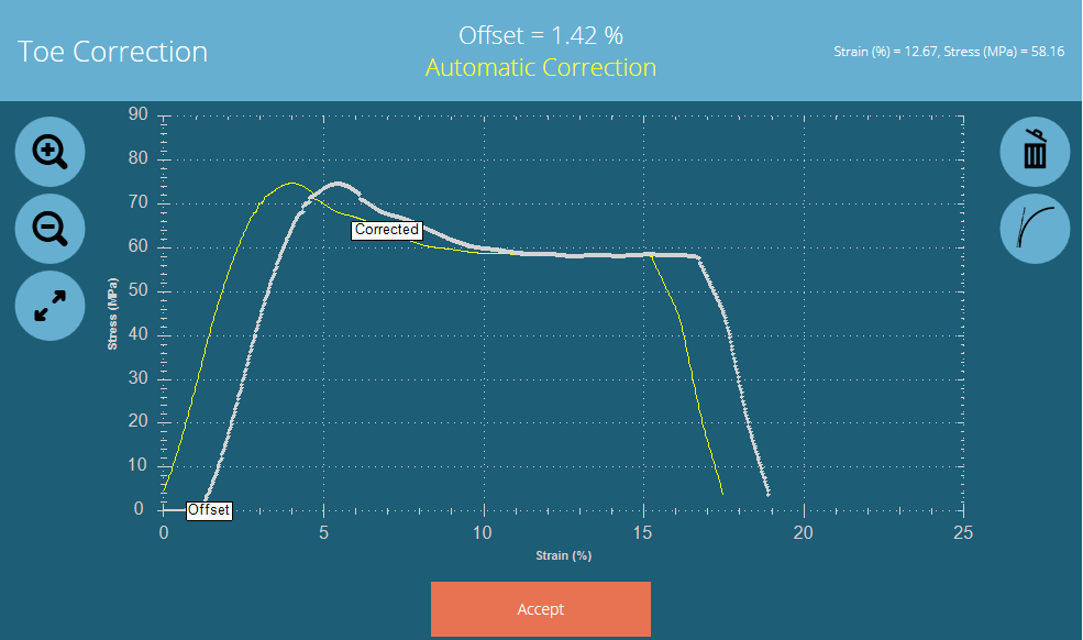
When the test sequence has ended, the screen above will be shown for 'Automatic Correction' and contain s the following information or functions:
- The value of the 'Offset' in percentage strain is displayed in the middle at the top of the screen. This is the value of strain (x axis) correction that has been applied
- Two traces are shown on the screen above. The white trace marked as 'Offset' is the original test plotted without compensation. The yellow trace marked 'Corrected' shows the new compensated trace
- The Zoom and resize tools can be used on the left-hand-side
The automatic calculation cannot be changed and the user must select 'Accept' button to acknowledge the calculation, apply the correction and close ths screen.
Any results that refer to the strain axis directly, or that use strain values to calculate results are automatically corrected by the offset value.
When viewing the Strain axis on-screen, the toe correction offset will be visibly applied and the corrected trace will be seen.
6.2.2 User User Defined 'On'
When set to 'On' the software uses a two-part Toe Correction operation post-test.
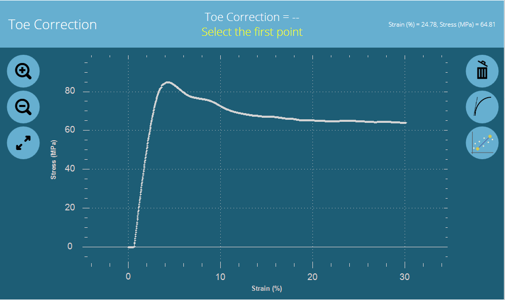
The user will be requested to select two points for which a cord line will be drawn between. This will determine a slope and ultimately the toe correction offset value and line which intercepts the strain axis.
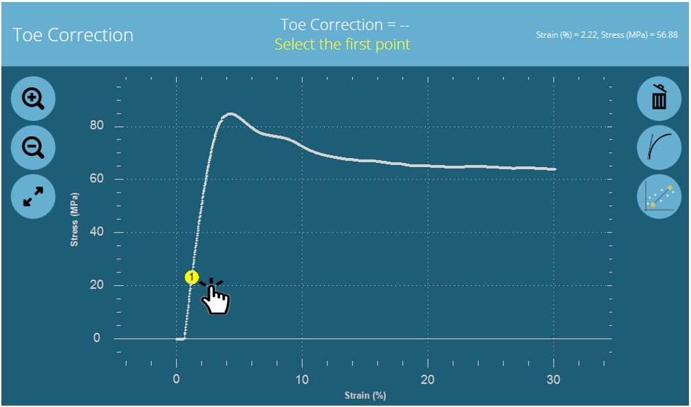 The first point is a lower value of stress (y axis).
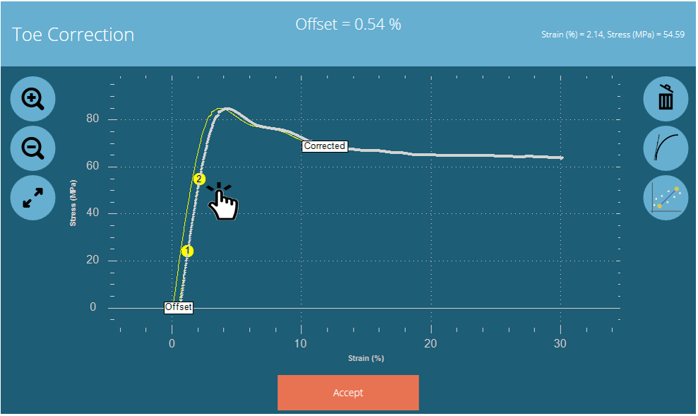 The second point is a higher value of stress (y axis).
Once the second point (higher value of stress), the display will automatically switch to show the manually calculated screen, which contans the following information or functions:
- The value of 'Offset' calculated from the manually selected data points, shown in upper-middle screen.
- Two traces are shown on the screen above. The white trace marked as 'Offset' is the original test plotted without compensation. The yellow trace marked 'Corrected' shows the new compensated trace
- The Zoom and resize tools can be used on the left-hand-side
- The right-hand trash-can icon will clear any currently selected points and return to prompt for first point selection
- The right-hand middle icon will apply an automatic calculation as shown previously (this will overwrite and manually selected points)
- The lower right-and icon will apply the manual calculation point 1 selection (will clear automatic calculation or clear previously manual selected points
Once the user has completed the selection points, pressing the 'Accept' button will apply the toe correction and close ths screen.
Any results that refer to the strain axis directly, or that use strain values to calculate results are automatically corrected by the offset value.
When viewing the Strain axis on-screen, the toe correction offset will be visibly applied and the corrected trace will be seen.
6.3 Vector Cloud Solutions
|
Icon(s) |
Action |
Settings |
|
|---|---|---|---|
|
Toolbox icon
Timeline icon
|
Insert/Action a Vector Cloud Solutions operation. |
|
|


If you require an operation or sequence of operations that cannot be accommodated by the standard operation set provided in VectorPro then it may be that Mecmesin can provide a VCS operation to achieve what you need. Contact your Mecmesin representative to find out more.
Vector Cloud Solutions is a service provided by Mecmesin where custom operations can be created and uploaded to the Vector Cloud for retrieval by the operator.
In order to take advantage of the test operation opportunities made available by VCS operations, you must sign up for an account with the Vector Cloud. This is easy and requires only your name and email address.
6.3.1 Signing Up for a Vector Cloud Solutions Account
The first time you click on the Vector Cloud Solutions icon on the Timeline toolbox you will be prompted to log into your account. If you do not already have a VCS account then you can sign up straight away. Simply click on the "add user" icon and you will be prompted with the following popup.


Enter your name and email address and provide a password (using at least one each of upper case, lower case, numeric and special characters). Once you have entered this information you will see the Validate popup

You will also receive an email with a six digit validation code. Enter the verification code in the popup and accept. You are now ready to log into your account.
Signing into your Vector Cloud Account
If you have previously signed up for an account with VCS, you can log in by entering your email address and password.
Successful login will result in the VCS window being shown. The contents of the library will vary depending on what the user has access to. The operations shown here are examples only.
The VCS Operations workspace has two tabs: All and Library. "Library" operations are those that have been created to be available to all users of VCS. "All" operations are those that have been created for specific customers and can only be accessed by them.

6.3.2 Downloading Vector Cloud Solutions Operations to your timeline
To use a VCS opeation in your timeline, simply double click or double tap on the desired operation and it will be inserted into your timeline at the cursor position.

To see more detail of what the VCS operation is designed to do, click on the "?" icon that appears when the cursor is placed over the operation icon. The information below is an example only and shows the ability for VCS operations to contain multiple languages to describe the operation.

Once in place, the test is operated normally.
6.4 Creating a Test Sequence

The ‘Timeline’ is where drag-and-drop operation commands from the left-hand ‘Toolbox’ are placed. This defines the test running sequence. In this instance the user has chosen to run a test that consists of:
|
|
|


This operation sequence can be seen in the green highlighted box in the images above.
- To remove operations from the timeline simply drag-and-drop the icon into the centre ‘trash’ icon.
- To remove all operations click the right-hand blue ‘trash’ icon.
6.5 Editing an Operation's Settings
To edit the operations above simply hover the mouse over the desired operation then click the green symbol once it appears. This action opens the ‘Edit’ menu (pictured below) which is used to configure the operation.

Each operation has parameters that can be edited. Such as displacement, target load, hold time and speed. Below is an example of an operation edit window; this is for a load based drive stage.
 |
|
6.6 Test Acquisition Settings
The ‘Settings’ menu located on the right-hand side of the ‘Operations’ screen (highlighted red on the image in the section 'Creating a Test Sequence') is used to configure various test parameters. Below is a table explaining these settings and the options available.
|
Icon |
Setting |
|---|---|
|
|
This icon is used to load system deflection compensation settings; click the folder to open the SDC explorer window and select the SDC settings. Click the cross to remove loaded settings. See the VectorPro Operating Manual - System Deflection Compensation User Manual for more information. |
|
|
With this feature 'OFF', the test time axis remains intact, including any time for operations for which data acquisition is switched off. With this feature 'ON', any time spent on those operations is removed from the test axis and all test data appears to be contiguous. |
 |
Data frequency – Alters the frequency at which the data is captured |
|
|
Time unit – Lets the user select the unit for time. |
|
|
Load unit – Lets the user configure the unit for load |
|
|
Displacement unit – Lets the user configure the unit for displacement. |
|
|
Speed unit – Lets the user configure the unit for speed. |
|
|
Stress unit – Lets the user configure the unit for stress. |
 |
Strain unit – Lets the user configure the unit for strain. |
 |
Load per unit time – Lets users configure their desired unit. |


7 Result
The ‘Result’ tab is where calculations used for data analysis and reporting are added. The ‘Toolbox’ area contains all the elements for producing results from test data. This window allows configuration of calculations as well as adjusting unit display settings.

The results screen populated with user-configured calculations and attributes.
Details of the elements that exist within the result screen are explained below. Some elements are application-specific and do not appear for stands without extensometry support. To edit an individual result click the edit icon located in the top-right corner of each individual result tile.
7.1 By Sample
These elements relate to the specimen and test setup, useful for tracking test details and system setup for example. Elements added here are also added to the report table. The elements include:
- Username: Adds the ‘Username’ of the person who undertook the test to the results screen,
- Timestamp start/end: Adds a timestamp for the start/end of the test to the results screen,
- Timeline: This is used to add details of the tests operations to the results screen. When the ‘Timeline’ icon is clicked on, within the post-test results screen, the user is presented with the operations for that test along with the settings used for that specific specimen.
- Specimen: Adds the dimension properties of the specimen to the results screen.
7.2 Attributes
These are the attributes attached to the specific test as configured earlier within the ‘Attribute’ tab. Elements added here are then available to add to reports. If an attribute within a test is not added to the ‘Result’ window, it will not be available to add to a report.
7.3 Standard Calculations
Standard calculations are based on the entire timeline and all data features. In all cases, name, axes, decimal place display, range and verify may be added:

| 1 | Name: Edit the display name for the calculation |
|---|---|
| 2 | Options: Enable ‘Hide Results’, ‘Hide in Report’ or additional 'Used by Other Results' (only available in Young's Modulus result setting) |
| 3 | Axes: Select the axes for the calculation |
| 4 | Decimal Places: Configurable from 1 to 9 |
| 5 | Range (Break): Define the boundaries for a calculation |
| 6 | Range (Break): Is used to give an alternate result at the calculated point. For example, this calculation has been setup to find break using ‘Load va Time’ but will give the ‘Result’ as ‘Strain’ |
| 7 | Verify: Enable to set a Pass/Fail boundaries for the calculation |
Peak and Trough calculations also include:
| Drop/Rise | Percentage of peak/trough value (including decimal values) |
| Occurrence | Peaks or troughs by time sequence |
| Order | Peaks or troughs by magnitude sequence (greatest = order 1) |
7.4 Calculations Available
|
Calculation |
Function |
|---|---|
|
|
The area under a curve. When load vs displacement, this represents energy or work done. With stress vs strain, this is equal to the toughness of the material or modulus of resilience (If calculation boundaries limit calculation to the elastic region). |
|
|
Trendline: the gradient of a straight line of best fit through all the data points within an x-range, and the y-intercept of this line. |
|
|
Trendline: the gradient of a straight line through the first and last data points within an x-range, and the y-intercept of this line. |
|
|
Mean (sum of all data values divided by the number of point values) |
|
|
The Break calculation returns the maximum load or displacement within a defined range before the end of a test. See below for more explanation. |
|
|
Peaks are defined by percentage drop after rising in y value. Here, select which peak in order of occurence in time sequence. |
|
|
The total number of peaks, this is defined by percentage drop and x/y range settings. |
|
|
The average value for all peaks within the defined boundaries. This is defined by percentage drop and x/y range settings. |
|
|
Troughs are defined by percentage rise after falling in y value. Here, select which trough by time sequence. |
|
|
The total number of troughs, this is defined by percentage rise and x/y range settings. |
|
|
The average value for all troughs within the defined boundaries. This is defined by percentage drop and x/y range settings. |
|
|
The value of 'y' axis for a specified value of 'x' axis or, the value of 'x' axis for a specified value of 'y' axis |
|
|
Peaks are defined by percentage drop after rising in y value. Here, select which peak by magnitude order. |
|
|
Troughs are defined by percentage rise after falling in y value. Here, select which trough by magnitude order. |
|
|
Maximum y-axis value within a range on the x-axis. |
|
|
Minimum y-axis value within a range on the x-axis. |
|
|
Percentage break, as defined using drop percentage. |
|
|
X-Intercept value at the percentage break calculated point, as defined using drop percentage. |
|
|
The value at operation result is used to return a specified value at the desired point on the operation timeline. |


7.5 Value at Operation Result

The value at operation result is used to return a specified value at the desired point on the operation timeline. Clicking on the edit button at the top right of the result opens the following window:

Within this operation, there are two additional important settings. First is the ‘Operation’ section. Clicking the magnifying glass opens an additional window where the desired operation that the result is to be determined from, can be selected. In the example above operation number 3 has been selected.
Within the ‘Result’ section an additional data point selection setting is also added. This option allows selection of whether the value is at:
- First data point recorded in the selected operation.
- Middle data point recorded in the selected operation.
- Last data point recorded in the selected operation.
In the example above the last data point from operation 3 would be reported, the result would be reported as a load value, as this is selected in the top ‘Result’ dropdown.
7.6 Break Definition
The Break calculation is an assessment of the rate of loss of load. A specimen may exhibit a peak or trough value before a break event, whereas a break is an ultimate failure to sustain sufficient load.
The range of time or displacement to be examined can be adjusted; this is entered into the ‘Break’ section. This value determines how far before the end of the test is analysed for the break value calculation.
7.7 Specimen Calculations
These are calculations that only apply to specimen specific values. The user can adjust the specific settings within the ‘Edit’ window as well as adding validation boundaries.
|
Calculation |
Function |
|---|---|
|
|
Offset yield is calculated using the Stress vs Strain graph and provides the intercept between a line parallel to and offset from the Young's modulus value. The user enters the offset value as a percentage in strain. |
|
|
Young’s modulus or modulus of elasticity, is a calculation derived from an algorithm that determines the greatest linear slope of the Stress vs Strain data, within specified boundary conditions. |
|
|
Calculates the strain value at a specified stress value, the x value is determined using an offset gradient from the Young's modulus calculation. It is expressed as a percentage of the original gauge length. |
|
|
Determines the break value using the algorithm from ISO 6892. |
|
|
Calculates the strain value at the ISO 6892 calculated breakpoint, the x value is determined using an offset gradient from the Young's modulus calculation. |
 |
Calculates ‘Ag‘ the percentage strain value of the plastic extension recorded at the maximum force point in accordance with ISO 6892. The line is calculated at the same gradient as the Young's modulus calculation. It is expressed as a percentage of the original gauge length |
 |
Calculates ‘Ae‘ the percentage strain value yield point measured over the distance from the start of yielding to the start of the uniform work-hardening, in discontinuous materials. In accordance with ISO 6892. It is expressed as a percentage of the original gauge length. |


7.8 Young’s Modulus Calculation Settings
Within the specimen result calculation settings for Young’s Modulus, there are two additional parameters that are required to satisfy some of the advanced result categories in some standards, for example, ISO 6892 Tensile Metals testing.

7.8.1 Used By Other Results
In the 'Options' category (highlighted in green above), by setting ‘Used By Other Results’ to ‘ON’, it will allow the use of the same slope gradient calculating Young’s Modulus, to be used to determine the calculation range and value for other associated results under the specimen calculation set.
These other results are currently:
- Offset Yield
- X – Intercept
- ISO 6892 Break Intercept X – Intercept
- ISO 6892 (Ag)
7.8.2 Use User Defined
This is in effect a range setting, which has two distinct ways of allowing Young’s Modulus to be calculated:
|
Use User Defined (range) |
Calculation Method |
|---|---|
|
OFF |
Calculates gradient slope using the automatically determined greatest slope |
|
ON |
Calculates the gradient slope by the user’s selected data points |
7.9 Young’s Modulus Calculation Method
Young’s Modulus is a measure of a specimen’s stress and strain relationship, namely the stiffness. It is determined by calculating a slope drawn through the data points of the stress vs strain analysis, during a specimen’s elastic region.
7.9.1 Greatest Slope Modulus
By default (before a test is run and with the range setting to off), the software will automatically determine the slope used by finding the greatest slope from the beginning of a test.
If the range setting is set to ‘ON’, the user can define their own range for determining the slope to calculate over. This covers two types of calculation method:
1. Chord Modulus
|
On test completion, the user selects from a graph axis view, two distinct points chosen on either the X axis (strain) or the Y axis (stress). VectorPro will then plot and report the slope value between the two closest recorded data points stored for that test. |
 |
2. Secant Modulus
|
The first point selected is an origin or zero value on the X-Y axes. The second point is a user-selected point on the X or Y axis. VectorPro will then plot and report the slope value between the origin and the closest recorded data point to the user selection. |
 |
The ‘use user-defined’ selection can be applied during the creation of a test, or can be activated as a post-test option.
7.9.2 Use User Defined (Pre-test)
If selected to ‘ON’ at test creation, no further settings are required and the result icon appears locked or faded as below.

When a test is subsequently run to completion, the user will be shown the Young’s Modulus definition screen. This screen cannot be exited or cancelled and the user must complete the selection of the data points when defining the slope.

The user-defined Young’s Modulus screen is shown at completion of a test.
Using a mouse or with an enabled touch screen, the user must move the cursor to the graph trace shown and select two data points to define the required slope.
The user must select positions on the actual data-trace shown and this will select the nearest data point to the cursor position at that time.
For more precision when selecting a point, the zoom keys can be used to enlarge the data plot area showing the individual data points more clearly.

An example of a chord modulus selected
Once the cursor is moved and a location selected, numbered markers ‘1’ and ‘2’ will be placed on the trace, highlighting the chosen data points. These indicate the start and endpoint of the slope definition. Corresponding X and Y coordinate values are displayed at the top of the screen for each data point.
If the user makes a mistake or selects the wrong position, then press the trash can symbol (shown above in red). This will clear the currently selected points and the user is free to make a new selection.
Should the user need to define a secant modulus, then the first point is selected by pressing the ‘+0’ button (shown below in green). This automatically places the zero or origin point on the trace and marks it as point ‘1’. The user then defines the second point by selecting it with the cursor. This is marked as point ‘2’.

An example of a secant modulus selected.
When the markers have been placed and the user is ready to process the result, pressing the ‘Accept’ button will apply these settings and create a result using the slope points defined.
7.9.3 Use User Defined (Post-test)
Once a test is completed, it is not possible for any level of user with any permission settings to change the status of the range setting between user-defined ‘ON’ and ‘OFF’. This is to protect the integrity of the defined test method in accordance with industry security policies such as for the CFR 21 Part 11 FDA compliance.
The user-defined result setting is protected by the test permission ‘Save’. If a user without save permission runs a new predefined test with the Young’s Modulus range setting ‘Use User Defined’ set to on, the software acts as shown in previous pre-test user-defined section.
However, if the test permission for Save is not set for the test and current user, then it is not possible for that user to edit this result post-test. Which means that selecting on the Young’s Modulus result window will not give a chance to reset the definition for the modulus method or slope range.
If a user that does not have ‘Save’ (edit) permission for the test, when they select the result window post-test, the screen will show with most parameter fields locked.
Limited changes can be made by the current user (dependent upon the test permissions assigned), but these are local only and will not affect the data base entry recorded for this result.

Limited result edit screen without save permission.
Any local changes made to this result during this time will be indicated by an asterisk * symbol in the result window. This denotes that the original method of displaying the result has been changed or modified.

An asterisk denotes modified result view.
If the user has the correct ‘Save’ permission for the test, then they are able, once a test has been completed, to edit the range settings again. To do this, either edit the test itself from the workspace or all tests area, or open an existing result in a test and edit the individual result setting for range use user-defined. Firstly select the area inside the result window (but not the graph icon).

Then select the graphic icon circled in red below.

The settings here are exactly the same as the ones defined in section 'Use User Defined (Pre-test)'.
A post-test edit also allows the user to accept or cancel the newly defined, range if the result is edited. Selecting cancel returns the user to the result edit screen.

An example of a post-test chord modulus screen.
7.9.4 Young’s Modulus Result Order
If the test setup has two Young’s Modulus results applied to it, for example:
- Automatic modulus method (Young’s Modulus standard result)
- Chord modulus (use user-defined)
The modulus result listed first in order on the test results settings screen (left to right, as shown below) will dictate which slope calculation is used if applying it to other results (used by other results). See the table at bottom of the page to show the Young’s Modulus result order and settings that affect other specimen results, sharing the same slope definition if ‘used by other results’ setting is enabled.

|
Young's Modulus Result Type |
Result Setting Order |
Used By Other Results |
Other Specimen Results Follow: |
|
|
1 |
2…or later |
|||
|
Standard |
✔ |
|
N/A |
Standard |
|
User-Defined |
|
✔ |
ON |
Standard |
|
Standard |
|
✔ |
N/A |
Standard |
|
User-Defined |
✔ |
|
OFF |
Standard |
|
Standard |
|
✔ |
N/A |
User-Defined |
|
User-Defined |
✔ | ON | User-Defined | |
Table showing the dependant results of Young's Modulus.
7.10 ISO 6892 Ae – (Percentage Yield Point Extension) Result Calculation
This is a new calculation and similar to the Young’s Modulus result, can give independent results between tests, when the user selects the user-defined range option.
This a specific calculation designed to meet the requirements of the ISO 6892 Tensile Metals test standard. (Extract shown below).

Figure 7 (from ISO-6892-1-2016) — Different evaluation methods for percentage yield point extension, Ae
| Ae | Percentage yield point extension |
|---|---|
| e | Percentage extension |
| R | Stress |
| ReH | Upper yield strength |
| a | Horizontal line through the last local minimum point, prior to uniform work-hardening |
| b | Regression line through the range of yielding, prior to uniform work-hardening |
| c | Line corresponding to the highest slope of the curve occurring at the start of uniform work-hardening |
The calculation reports the difference between the upper yield point and the intercept of the work hardening region to the last trough detected and is reported as % of the original sample gauge length
By default, this result is automatically calculated if selected, when the test is completed.

Should the user select the user-defined range option, this will invoke a user input screen that requires manual selection of data points using a mouse or touch screen cursor.
The order of entry is:
- Upper Yield
- Last Trough
- The first point of hardening
- The second point of hardening
If a mistake or an incorrect data point is selected, pressing the trash icon will clear all currently selected points and allow the process to restart from the beginning.
The zoom and resize icons are also active and using the cursor, the trace may be scrolled.

Ae user-defined screen showing completed data selection.
After each data point is selected, the corresponding x-y coordinates are shown at the top of the graph screen. When the correct points are selected, pressing the Accept button will complete the result configuration.
As with the Young’s Modulus result, the user and test permissions determine who can edit a test and who can access the range settings in the Ae result setup.
7.11 Verification of Calculations

Within the calculation ‘Edit’ window it is also possible to set up verification ranges that can be used to verify whether the data is above, below or within a specified range. Details on how to view verify whether a result is within the verification boundaries can be found in the 'Calculations Results' section located in the VectorPro - All Tests Viewer and Results Viewer User Manual.
7.12 Formula

Within VectorPro it is possible to create custom calculations using the output from other standard and specimen calculations. This is achieved using the ‘Formula’ calculation, first drag and drop the tile (See above) into the ‘Formula’ section.
Once the formula result is in place. Select the edit icon located in the top-right corner of the individual formula icon to configure the calculation.
Custom results can be created using the drag and drop formula result.
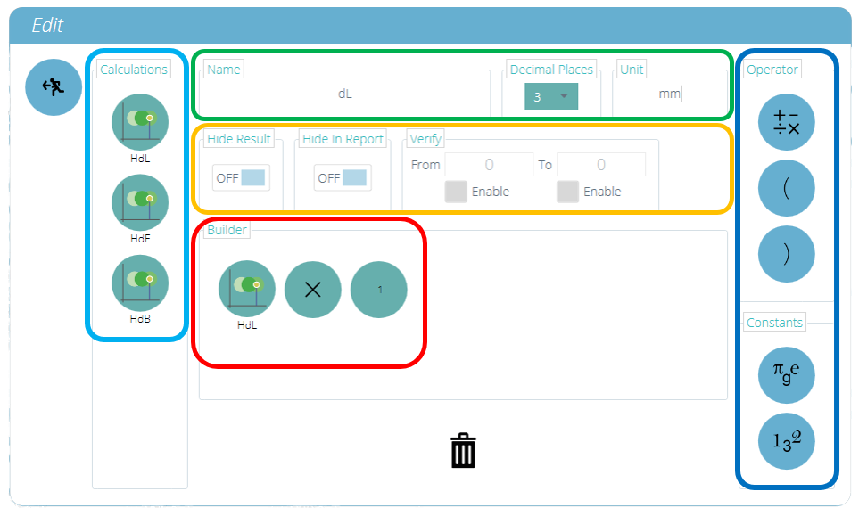
The window, shown above will be displayed on the screen. Using this window a formula can be constructed using the following sections:
Input Calculations (Highlighted in Light Blue) – The input calculations consist of calculated results from other standard and specimen calculations currently configured within the ‘Results’ window.
Input Operators and Constants (Highlighted in Dark Blue) – These operators and constants are used with the input calculations to build the formula.
Operators available include:
- Add: +,
- Subtract: -,
- Divide: ÷,
- Multiply: ×,
- Brackets: ( ),
Constants available include:
- Pi (Π): Value of Pi to 9 decimal places (3.141592654),
- Gravitational Constant (g): Earths gravitational constant (9.80665 m/s2),
- Euler’s Number (e): Value of Euler’s number to 9 decimal places (2.718281828),
- Custom Constant: Selecting the icon pictured below enables entry of a custom constant,
Result Hide and Verify (Highlighted in Orange) - Select whether individual formula results are visible in results display or reports. Add a verification range to individual formula results.
Formula Builder (Highlighted in Red) – This section is used to build the formula, input calculations, operators and constants are placed here using intuitive drag-and-drop control,
Calculation Definition (Highlighted in Green) – This section is used to define the calculation; set the name, number of decimal places and an applicable unit for the calculated result.
7.13 Building a Formula Result
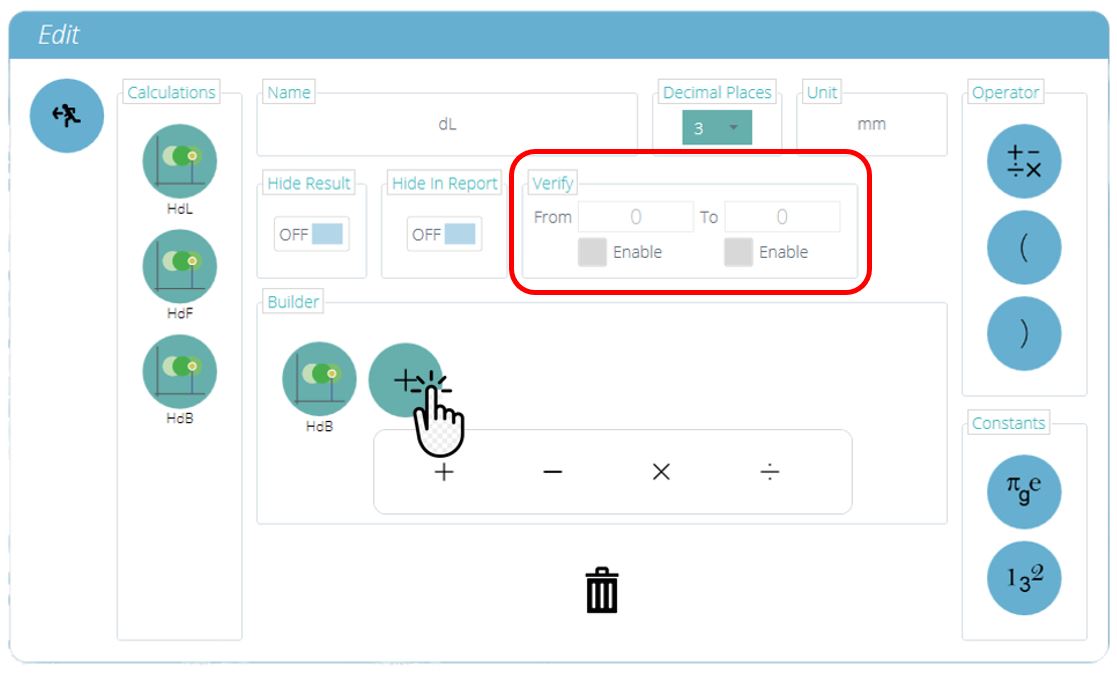
To create a formula result drag and drop elements into the central space:
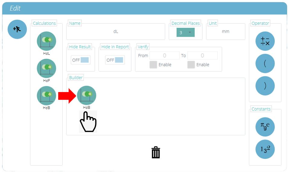
To configure an operator/constant, place the desired component into the formula builder, then click on the component to reveal the operator or constant settings menu. As shown in the image below:
To save the formula press the back icon located in the top left of the ‘Edit’ window.
7.14 Example Calculation

In the image above the load change for the test is being calculated by subtracting the result of the ‘Value @ Operation’ calculation from the result of the ‘Max’ calculation.
The given result is the load difference between the end of the pre-load stage and the maximum reading for the test.
The formula has been named ‘Load Change’ and uses the units ‘N’, the result will show 3 decimal places. The input calculations are configured as followed:
- The ‘Max’ calculation is configured to give the maximum load for the test,
- The ‘Value @ Operation’ calculation is configured to give the load at the end of the pre-load stage.
7.15 Hide Result & Hide in Report Functions
When the options ‘Hide Result’ or ‘Hide in Report’ are used, the displayed result data acts in a different way. It is important to understand how these features (if enabled) affect the appearance of the software in a test definition.
7.15.1 Hide Result
For example, a formula is required to calculate a specialist result for “Force Decay Due to Time” according to EN14704 test standard.

Where:
- V is the max force in the final cycle
- W is the max force in the final cycle after the hold time
Firstly, the two results for V and W are determined. Using the result below V is a Peak occurring in the 5th cycle.

W is a 'Value at Operation' on the last cycle, which in timeline sequence is operation number 10. This is shown in the result below:

Next, create the formula to find A the force decay value. To do this use a formula function, as shown below: 
When results are shown in the VectorPro results area, all of these values are seen. The user can leave all results displayed, but if a complex formula has had many creation steps, it can be useful to hide selected results and only show the complete required result to export or use in a report.

To hide a result:
- Either edit a test and go to the results screen direct, edit a result calculation and select hide,
- In the result view select the region outside of the graphic and inside the result window (shown in orange above), to display the edit result screen and select ‘Hide Result’ toggle switch to ‘ON’.

7.15.2 Hide in Report
Each test result contains the ability to be hidden from a report or an export of the result data to CSV or Excel.
This is set in the same way as the hide option detailed above. The ‘Hide in Report’ setting can be implemented by editing a test directly and navigating to the results settings, or by selecting the outer area of a result field at the view results screen.

In the image above, the 'Hide in Report' option is off for all results. The 'Hide in Report' setting can be configured using the switch of any desired result, as shown below.

This will hide the result from any report. In the example below the result for 'Offset Yield' has been hidden.

When viewing a result file, an export, or a report, it may not appear obvious that a test definition has some hidden results included. VectorPro provides a method for users with appropriate permission levels to validate this.
If there is need to check whether there are hidden result elements contained within a test, then the test must be edited, with the permission to edit a test enabled for that user.
In the previous example, the result ‘Offset Yield’ was hidden and the permission to hide in report enabled.
To check the hide options for a particular test, the test setup is edited from the workspace or all tests listing.
Then select the Results tab in the test setup view. All results will be listed here, with extra information on those that are currently hidden.

3 results listed for this test routine (one hidden).
The Offset Yield result that was chosen with 'Hide 'options has two struck-through eye symbols to denote the hidden feature is enabled.

| 1 | Denotes that the Hide Result feature is enabled |
| 2 | Denotes that the Hide in Report feature is enabled |
7.16 Sequence of Calculations
Calculation results are ordered on screen and in reports as laid out here. Calculations on the far left will be at the top of the ‘Results’ screen and calculations on the right will be at the bottom, bear this in mind when setting attributes on the ‘Result’ editor screen.
7.17 Units and Polarity
On the right-hand side of the main screen the selection of the units and axis polarities for this test is available:
|
 |
7.17.1 Test Polarity Tension

In a tension test, the upward motion is positive (blue arrow), with downward being negative (green arrow).
7.17.2 Test Polarity Compression

For a compression test, a downwards motion is positive (blue arrow), with upward being negative (red arrow).
8 Report
The screenshots illustrated in this section are using an OmniTest-5.0 and show the features available to this test stand.

The report Toolbox is populated with attributes added within the ‘Result’ window.
Simply drag-and-drop elements into the predefined areas on the report screen to select those required to appear in the PDF and printed reports.
 |
To view and export the completed report simply navigate to the ‘Results’ page for the desired test and click the ‘Report’ button (Pictured left). |
For more information regarding exporting reports and data, see the VectorPro - Running a Test, Reporting and Exporting User Manual.
Preparing the report layouts has three main stages:
- Populate the report toolbox,
- Populate the report template,
- Position the elements and configure reporting options.
8.1 Populating the Report Toolbox

A report can include any attribute attached to a test. The default attributes available in any test are:
- Test name (the same for all versions),
- Test description (can vary by version),
- System (test system or instrument used).
These can be supplemented by any other custom attributes (image, label and note). Tables of results and graphs are available by default in every report.
The image above shows an example scenario where the user has added 3 ‘Attributes’ to their ‘Result’ screen, these will now be available on the ‘Report’ designer screen.
To populate the ‘Report’ follow the steps below:
- Begin in the ‘Result’ tab within the ‘Test Designer’ screen. Then simply drag-and-drop attributes or calculations into the main screen. Attributes and calculations have to be placed within their corresponding section on the main screen.
- Go to the ‘Report’ tab, to find the selected attributes in the ‘Toolbox’, next to a blank page.
- Drag attributes onto the blank page into the desired position. These can be refined, alongside graph and results table at the next stage. For ‘Report’ configuration see the next page.
8.2 Report Configuration
Dividers (highlighted below) can be removed or added by clicking them and attributes can be deleted by selecting the ‘Trash’ icon at the bottom of each attribute.

Below these elements, the report will display a table of all selected samples, followed by a graph of up to eight samples (The number of displayed samples can be changed in the right-hand plane).
Additional samples appear on subsequent pages in sets of user-defined samples.
|
Located on the right-hand side of the screen is the report ‘Settings’ menu. From here the user has the ability to change several other elements, such as:
|
 |
Selecting ‘Show Prompt for Values’ enables these attributes to be exported via Email, Excel and PDF.
|
To view and export the completed report simply navigate to the ‘Results’ page for the desired test and click the ‘Report’ button (Pictured left). |

| 1 | Exit |
|---|---|
| 2 | Print Report |
| 3 | Save as PDF |
| 4 | Go to page number shown |
Reports are laid out with user-placed elements on page 1, followed by tabulated results and a graph. Up to eight samples are shown per page, up to a further eight on the next page and so on. Statistical results are shown below the final table.

By default PDF reports are saved to C:\ProgramData\Mecmesin\VectorPro\reports
9 Permissions
The test ‘Permissions’ tab works in the same manner as the main ‘Permissions’ control in VectorPro. Simply drag users into the cards to grant permissions to: save test copies and edits, execute the test, view the report, print (export) reports or delete samples.

In the example above, ‘Jane Smith’ and ‘Chris Howard’ can manage all aspects of this test, whereas the group ‘Night Shift’ has limited permissions. To remove a user from a card simply drop them into the trash located at the bottom of the screen.
It is important to ensure that if a user is required to execute a test that they have access to both ‘Execute’ and ‘Workspace’ permissions as well as access to the test system being used, this is configured in the main ‘Permissions’ screen. For more information relating to verification boundaries please refer to the 'Attributes Permission screen interface' section located in the VectorPro - Workspace and User Management User Manual.
The ‘Workspace’ permission places a tile for the test being edited in the user’s workspace, by default this is always created for the user who created the test. It is possible for a user to access tests without having the ‘Workspace’ permission by using attribute permissions. This is fully explained in section 'Grouping Attributes - Creating Test Folders'.
A user with permission to access the ‘All Tests’ viewer can also see a list of all tests and subsequent versions of each test but, is only able to use tests and versions for which they have permission.
9.1 Prompt for Authorisation Settings
For certain functions, such as saving a test and deleting samples, it is possible to assign a user the ability to carry out the function only with direct action from another user with ‘authorisation’ rights.

To do this place the user on the left-hand side of the permissions card, shown above. Users on this side of the card require permission to carry out the designated function, expect ‘admin’.
Users on the right-hand side ‘authoriser’ section of the card have the ability to carry out the function (in this case saving the test) and they also have the ability to grant authority to users on the left-hand side to carry out this function.
In the example above, 'Jane Smith' and 'Chris Howard' have permission to save without authorisation and can authorise the action of other users. Users in the 'Night Shift' and 'Day Shift' groups can only save with authorisation from users on the right.
If a user contained within the ‘Day Shift’, for example, attempts to save a test they will be presented with the ‘Prompt for Authorisation’ sign off window shown in the next section.
Please Note: In instances where users are on both sides, they may be part of a group on the left-hand side but be as an individual on the right, the user will have always have ‘authoriser’ permission. For the above example, Jane Smith is located on both sides as her user account is contained within the ‘Day Shift’ group. This is located on the left-hand side and requires permission to carry out the function. As Jane Smith’s user account is also located on the right-hand side she does not require permission and can carry out the function with no additional input action.
9.2 Prompt for Authorisation Sign Off

When a user who requires authorisation carries out a function the following pop-up will appear on the screen. Here there are three entry fields:
- Authoriser: The top drop-down section allows selection of the desired authorisation account,
- Password: The middle section is where the selected user enters their login password,
- Authorisation note: This is where the authoriser can enter a note detailing what action has been taken. It is required that accept or decline are selected for this note to be saved.
At the bottom of the screen, the user is presented with three actions. These allow the user to:
- Accept the change made and save the note to the event log,
- Decline the change made and save the note to the event log,
- Cancel the change, the note will not be saved but all actions are still logged in the event log.
The note entry saved can be viewed in full in the event log along with the details relating to the change such as the user who asked for authorisation. The user who authorised the change, the time and date or the event and what was changed.
10 Saving a Test

When the Test Design function is exited, the screen presents a pop-up box pictured below and asks if save changes are required. The ‘Yes’ command saves the test and increments the version number.
There are certain factors to be aware of when saving a test:
- If a test name is changed, it only applies to the latest version of that test. Previous versions remain linked to this test, but the previous version’s test name will be shown when viewing versioning history.
- When an attribute or calculation is added or removed, or test parameters changed, these are not applied to previous versions of the test.
- The test version that is edited becomes the new version (e.g. a test reaches version 5, and version 3 is then edited – this edit becomes version 6 and changes added to versions 4 and 5 are therefore not included).
10.1 Override Test Version
Within VectorPro, it is possible to override a version of the test when saving it, rather than having to increment the test version.
When exiting a test, which is being edited, the pop-up box pictured above appears, the ‘Yes – Override Version’ option allows saving of any changes made, without incrementing the version number.
This feature is useful if the changes are minor or if the user is developing a test method.
Permission to allow test versions to be overridden may be configured. To do this simply drag-and-drop users into the override version card in the general permissions screen. This enables the ability to override test files, or remove them from the card to take away their permission. This is useful for protecting tests from being changed without incrementing the version.
10.2 Adding Change Notes to Saved Tests
In addition to the override feature, there is also a ‘Change Note’ field within the save confirmation window. The change note field is an area where text entry detailing the alterations that have been made.
This is saved with the test and can be viewed in the ‘All Tests’ window and ‘Test Results’ screen as well as being stored in the event log. Change notes are only saved when clicking either ‘Yes’ or ‘Yes – Override Version’. Please note there is a 300-character limit.
To view change notes on the ‘Test Results’ screen, simply click the arrow icon (Circled) to expand the field and display the change note for the selected test version.

‘Test Results’ viewer showing the change note for the latest test revision.
11 Further Information
For more information relating to VectorPro, please return to the User Guidance section of this user manual and continue to the next applicable user manual.