1 Vortex-dV Motorised Torque Test Stand Operating Manual
 |
431-468 April 2020 |
2 Introduction
VectorPro™ and VectorPro™ Lite are registered trademarks of Mecmesin Ltd.
This document refers to Mecmesin Vortex-dV test stands operating the latest firmware version.
The following manuals may aid you in the use of your test stand:
|
|
|
Advanced Force Gauge (AFG Mk4) Operating Manual (431-213) Runs through the operation of Advanced Force Gauge in conjunction with Vortex-dV test stands. |
 |
 |
VectorPro™ User Manual - Introduction and Initial Setup (431-955) |
2.1 User Manual Icons
Throughout this manual, the icons shown below are used to identify important health and safety information as well as additional installation/operation guidance. Do not proceed until each individual message is read and thoroughly understood.
2.1.1 Warning
2.1.2 Caution
2.1.3 Information
- 1 Vortex-dV Motorised Torque Test Stand Operating Manual
- 2 Introduction
- 3 System Diagram
- 3.1 Identifying the Model of Vortex-dV
3 System Diagram
3.0.1
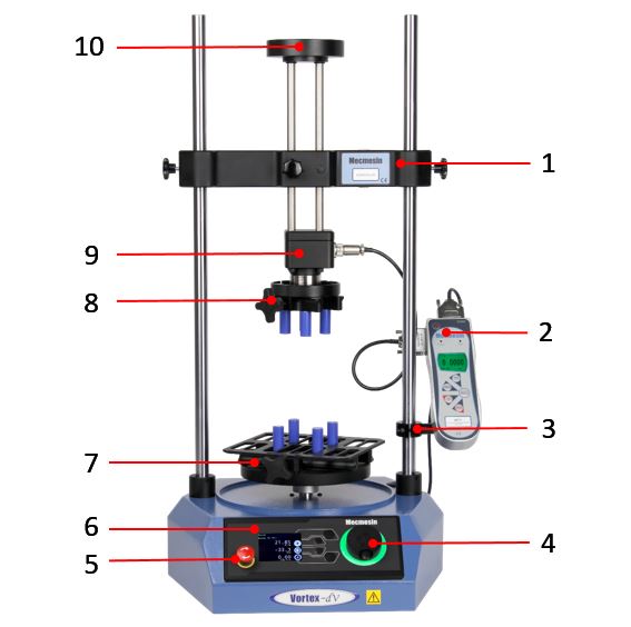
| 1 | Adjustable crosshead |
| 2 | AFTI (Advanced Force / Torque Indicator) |
| 3 | AFTI Mounting bracket |
| 4 | Multi-function scroll wheel |
| 5 | Emergency stop button |
|
6 |
Front panel control |
| 7 | Lower fixing plate. (optional) Shown with saddle plate |
| 8 | Upper fixing plate (optional) |
| 9 | Static torque transducer |
| 10 | Top load tray (height adjustable) |
3.1 Identifying the Model of Vortex-dV
The Vortex-dV has been through minimal design changes from it's inception. However, please see the sections below to assist in clearly identifying the exact model.
3.1.1 Mark 1
Vortex-dV Mark 1 machines are the original motorised torque stands developed for use with the AFTI digital force/torque indicator. These are controlled by VectorPro Lite functionality (as well as the stand-alone operation). These stands were produced up to April 2020 and will have formatted serial numbers up to 20-XXXX-04.
These are identified by the rear panel shown below:
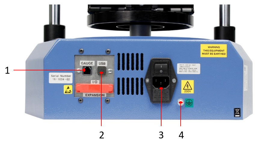
| 1 | AFTI (Advanced Force/Torque Indicator) input |
| 2 | USB connection for PC control using VectorPro™ software |
| 3 | Mains connection and Inlet Filter (contains voltage selector and fuse holder) |
| 4 | System earth point |
3.1.2 Interlock Enabled
These are very similar to the Mark 1 model stands, but now incorpoarte the new 'Sensor' and 'Interlock' connections. These machines are produced from May 2020 and will have formatted serial numbers from 20-XXXX-05.
These are identified by the rear panel shown below:
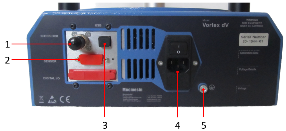
| 1 | 'Interlock' connection (interlock override plug shown fitted) |
| 2 | 'Sensor' connection. |
| 3 | USB connection for PC control using VectorPro™ software |
| 4 | Mains connection and Inlet Filter (contains voltage selector and fuse holder) |
| 5 | System earth point |
4 Unpacking and Parts Supplied
4.1 Inspection and Unpacking
Before installing or operating the Vortex-dV system ensure that no visible damage has occurred during the shipping of the device
4.2 Packaging
We strongly recommend that the packaging is retained, as this can be useful if the machine needs to be returned for calibration or shipped to another location.
Parts supplied with the Test Stand, details the parts that should be included with your test stand. Please contact Mecmesin or your authorised distributor if any items are missing or damaged.
4.3 Moving the Test Stand
4.4 Parts Supplied
Please see the table below for the list of parts supplied with the Vortex-dV system.
| Item | Quantity |
|---|---|
| Vortex-dV test stand is supplied with a pre-selected torque transducer (1.5, 3, 6, or 10 N.m) | 1 |
| AFTI gauge bracket (for fitting an AFTI torque indicator to the column) | 1 |
| Hex key for tightening crosshead to gauge bracket | 1 |
| Mains cable | 1 |
| Document: A Guide to Safe Use of Mecmesin Mains Powered Test Systems | 1 |
| Online Manual Information Guide | 1 |
4.5 Accessories
For a full range of digital force gauges and accessories, please go to the Mecmesin website: help.mecmesin.com, or your local distributor.
- For connection of the stand to your computer, a Mecmesin supplied 2m USB-B to USB-A cable communications cable is required, (part no. 351-093),
- For a Mark 1 Vortex-dV - Use communications cable (part no. 351-092) to connect the Mecmesin Advanced Force and Torque Indicator (AFTI) to the Vortex-dV.
- For an Interlock enabled Vortex-dV - Use communications cable (part no. 351-103), to connect Mecmesin Advanced Force and Torque Indicator (AFTI) to the Vortex-dV.
5 Initial Setup
5.1 License Key
A VectorPro Lite license key is required to run a Vortex-dV test stand (fitted with an AFTI) and VectorPro software.
5.2 Locating the Stand
The test stand should be positioned on a suitable, level, stable work surface.
5.3 Mains Power Supply
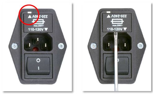
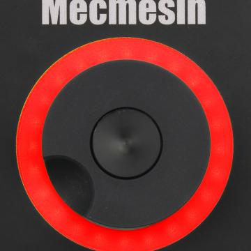
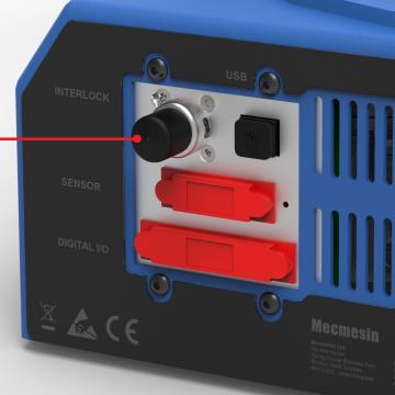
Vortex-dV test stands can be used on 110–120 or 220–240 Vac 50-60 Hz supplies. The rear fuse carrier is set for your local requirement but is reversible. Should you replace a fuse, ensure the correct local voltage is selected.
The voltage that is selected is indicated by which the arrow is pointing to the white line located at the bottom of the device. This is illustrated in the image below, shown within the red circle:
5.4 Fuse Specification
A Vortex-dV test stand uses two 2A - Time-delay (T), 5 x 20mm fuses. If replacing a blown fuse only replace the fuse on the active side of the inlet filter with the fuse specified above, or equivalent.
If you are in doubt, please contact your local Mecmesin support agent for more information.
5.5 Attaching the Torque Sensor
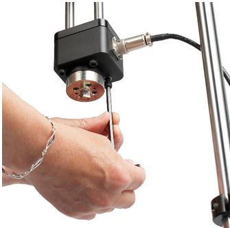
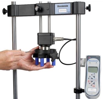
The torque cell attaches to the crosshead using the four supplied M6 caphead screws. To fit the torque cell, first, ensure that the cable exit is towards the side that you plan to fit the AFTI.
Then, align the transducer with the mounting plate and secure using one the M6 bolts, if needed have one person hold the transducer while the other fits the screws. Make sure the transducer is seated centrally before fulling tightening all of the screws.
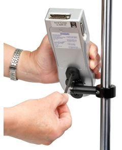
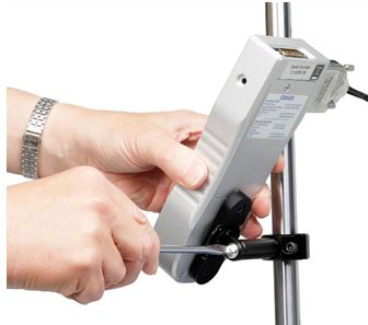
5.6 Fitting the AFTI Torque Indicator
The AFTI can be fitted to either the left or right-hand of the test stand, but it is important to ensure that the cable coming from the transducer points to the side that the gauge is mounted, as this prevents any unnecessary kinking.
The fixing bracket can be easily fitted, adjusted or removed and transferred to the opposite column using a 4 mm Hex key to loosen the retention screws.
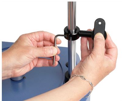
To fit the AFTI to the bracket use the two supplied screws. These pass through the bracket into the back of the gauge and are secured using a 4mm Hex key. The angle the AFTI sits at can be adjusted by loosening the screw located on the side of the bracket.
5.6.1 Connecting the AFTI and the Vortex-dV
First, connect the transducer to the side port of the AFTI, using the cable from the transducer.
Connect the top port of the AFTI to:
For a Mk1 Vortex-dV - the RJ11 port marked ‘Gauge’ on the back of the Vortex-dV, using the supplied cable, (part no. 351-092).
For an Interlock enabled Vortex-dV - the 15 way 'Sensor' connection on the back of the Vortex-dV, using the supplied cable (part no. 351-103).
5.6.2 AFTI Communication Settings
To achieve communication between your Vortex–dV test system and your AFTI gauge you need to apply the correct settings within the AFTI’s communication menu (BAUD rate must be 115200). Use the following steps to configure the AFTI:
| AFG Button | Button Name |
|---|---|
 |
UNITS/MENU |
 |
ZERO/DOWN |
 |
RESET/ENTER |
 |
MAX/ESC |
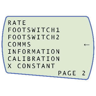 Press 'UNITS/MENU' once to continue to menu page 2, as shown in the image above. Scroll down using the 'ZERO/DOWN' button, then press 'RESET/ENTER' to select the 'COMMS' menu.
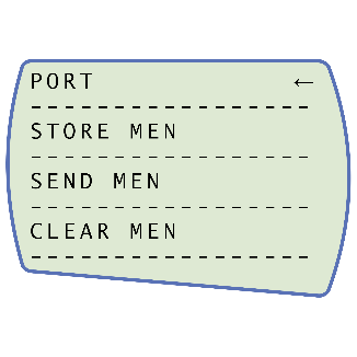 Now press 'RESET/ENTER' on 'PORT'.
 Set 'TX UNITS' to 'ON', press 'RESET/ENTER' to continue.
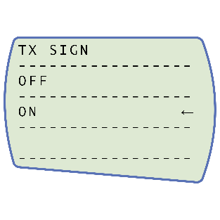 Set 'TX SIGN' units to 'ON', press 'RESET/ENTER' to continue.
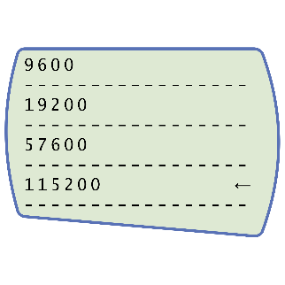 Set the baud rate to '115200', press 'RESET/ENTER' to continue.
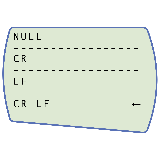 Set 'CR LF', press 'RESET/ENTER' to continue
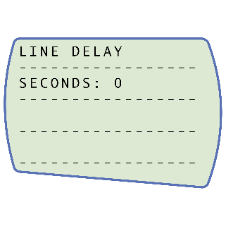 Ensure the line delay is set to '0', press 'REST/ENTER' to continue.
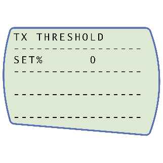 Ensure the TX threshold is set to '0', press 'REST/ENTER' to continue.
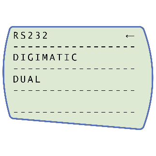 Set 'RS232', press 'RESET/ENTER' to continue.
5.7 Connect the Test Stand to a PC (VectorPro Users Only)
If you are using VectorPro software, connect the USB B port, located on the test stand, to a PC using an appropriate cable (part no. 351-093).
|
Important! Please install VectorPro software on the assigned PC before connecting the test stand to that computer. Once the software is installed and the stand is connected, the stand will show as connected. This is shown in the image to the right.
|
 |
5.8 Cable Management
It is essential that no cables interfere with the controls or any moving parts. Failure to do so could lead to injury or damage to the equipment.
5.9 Attaching Grips and Fixtures
The most commonly-used upper fixture used is the 100 mm upper fixing plate with a diameter capacity of 10 mm to 78 mm. This is fixed to the adaptor on the torque transducer using a 2.5 mm Hex key to secure the four countersunk screws supplied.
The most commonly-used lower fixture is the 188 mm diameter lower fixing plate with a diameter capacity of 10 mm to 190 mm. This is fixed to the Vortex-dV spindle using a 2.5 mm Hex key to secure the four countersunk screws supplied.
A range of other torque testing fixtures is available, including saddle plates that help support samples in the fixing plates, longer grip fingers, mandrels, and chucks.
5.10 Test Stand States
The test stand can be in one of five states:
1. Test readiness - ready to start, or complete,
2. Testing – test operation sequence is running,
3. Stopped - test interrupted or emergency stop pressed,
4. Jog mode - for jogging or positioning the crosshead manually,
5. Settings menu – for adjusting your test stands settings,
In each state, the selector buttons have functions described by the on-screen icons.
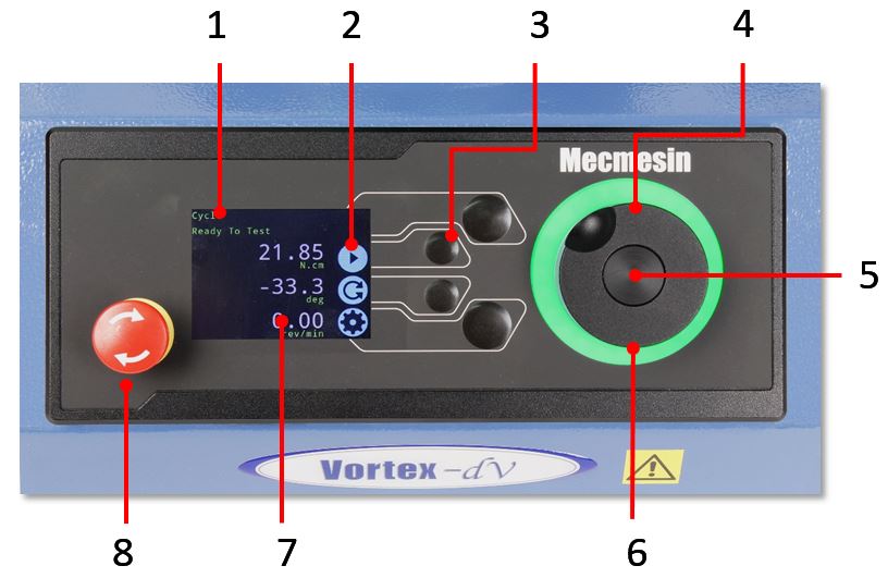
6 Front Panel Controls
|
1 |
Status messages and information |
|---|---|
| 2 | Button function icons |
| 3 | Multi-function selection buttons |
| 4 | Multi-function scroll wheel |
| 5 | Scroll wheel button (used in function menus) |
| 6 | LED dial status ring |
| 7 | Colour display |
| 8 | Emergency Stop button |
6.1 Emergency Stop Button
 |
Push to stop the crosshead movement. Rotate the button to release it and resume crosshead control. If pressed during a test, do not restart a test, ensure you remove any residual force using the test stand’s jog controls. |
6.2 Multi-function Scroll Wheel Control
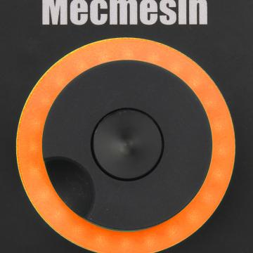
6.2.1 Scroll Wheel Colours
The lights surrounding the wheel illuminate in three colours, indicating the status of the test stand:
 |
 |
 |
| Colour | Status | Indication |
|---|---|---|
| Green | Pulsating | Ready to start a test |
| Green | Rotating | Scrolling through menus |
| Green | Flashing | Test completed |
| Amber | Static | In jog mode menu |
| Amber | Rotating | Lower spindle moving |
| Red | Static | Test aborted/limit triggered |
6.2.2 Jog Mode
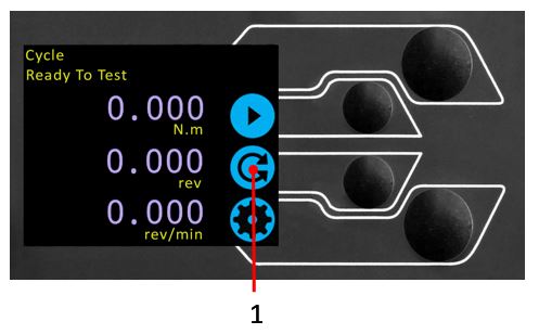
When in jog mode the wheel drives the Vortex-dV clockwise or anticlockwise, matching the direction the wheel is turned. This method offers more variable control when compared to the two fixed-speed jog control buttons (circled in red below).
 |
 |
| 1 | Enter Jog Mode |
|---|---|
| 2 | Jog keys 'Clockwise' and 'Anti-clockwise' |
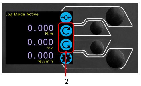
The scroll wheel can also be used as a speed controller. The jog buttons move the spindle at the set speeds (configured in the ‘Jog Settings’ menu picture below). Rotating the wheel clockwise while holding a jog button increases the speed and rotating the wheel anticlockwise while holding a jog button decreases the speed
Vortex-dV test stands also feature a precision jog mode, rotating the scroll wheel while holding the central scroll wheel button moves the test stand at its minimum speed; this is useful when fitting specimens into grips for example.
6.2.3 Navigational Control
The scroll wheel can also be used to navigate the menus. When in a selection menu, the scroll wheel cycles through the selections and their values. This is an alternate navigational option to using the up and down arrow buttons.
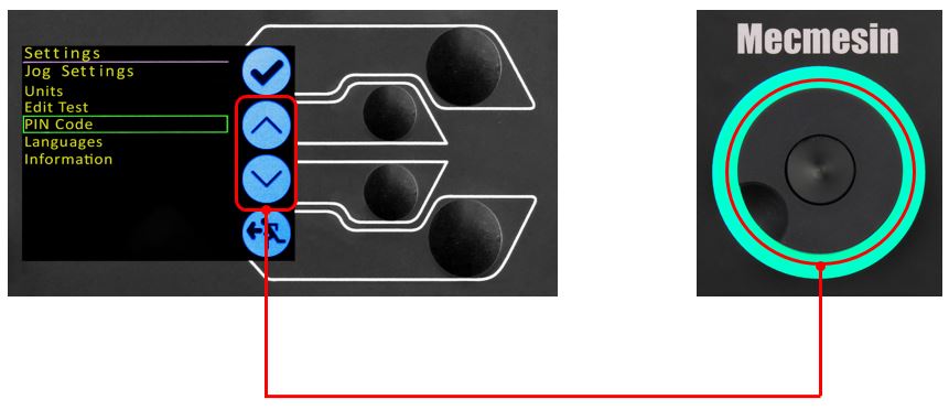
6.2.4 Central Button
The central button is used to confirm a menu selection. It is equivalent to the tick button function.
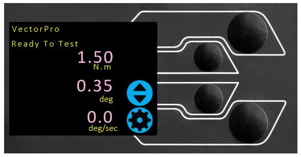
6.3 Vortex-dV Display Panel
The display indicates the stand’s status, displays live values and is used to configure the test stands settings.
The purpose of the four multi-function button is indicated on screen by an adjacent icon. Below is an image showing a typical example of the on-screen icons in relation to the physical buttons.
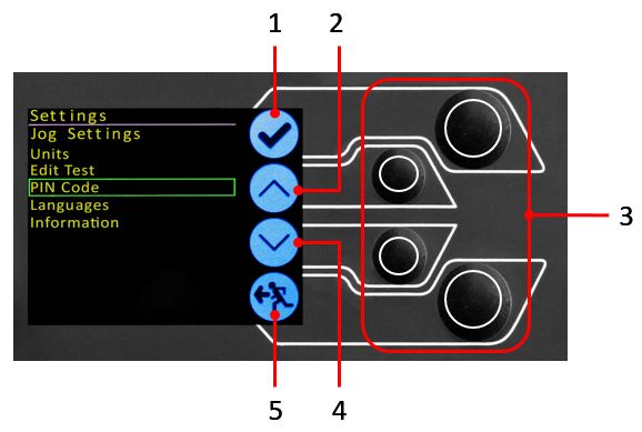
| 1 | The top icon is 'Confirm' |
| 2 |
The mid-upper icon is 'Up' |
| 3 | 'Menu selection' buttons |
| 4 | The mid-lower icon is 'Down' |
| 5 | The bottom icon is 'Back/Exit' |
6.4 On-Screen Icons
On-screen icons vary depending on the current state of the test stand. What functions the physical buttons perform at that point, depends upon which menu is currently displayed. Below are reference tables to help explain the icon definitions, in relation to the test stand state.
6.4.1 Pre-Test
|
Icon |
Action |
 |
No AFTI connected. |
 |
Start a test sequence |
 |
Enable jog mode |
 |
Go to settings |
 |
Move to the home position (Set within VectorPro or test start position) |
6.4.2 During a Test
|
Icon |
Action |
 |
Pause test - This stops the lower spindle movement, leaving the stand in a state of test readiness. The status message is ‘Interrupted: User’ and the 'Play' and 'Stop' buttons will be displayed. |
 |
Stop test - This will abort the current test running (including the VectorPro software). The status message is 'Test aborted' and the 'Home' and 'Exit' buttons will be displayed. |
|
Emergency stop button pushed: Message: ‘Emergency Stop!!!’. Release the emergency stop to regain control and remedy the situation before resuming testing. Note there is no on-screen icon for the emergency stop. |
6.4.3 Pause/Stopped
|
Icon |
Action |
|
Continue test sequence. |
|
Stop test - Shown when the Pause button is pressed. This ends the test at this point. |
|
Move to the home position (start position from the beginning of the previous test) -This icon is only visible after pressing the 'Stop' button. |
 |
Exit to the test ready screen, leaving the crosshead in its current position - This icon is only visible after pressing the 'Stop' button. |
6.4.4 Jog Mode
|
Icon |
Action |
 |
Zero (tare) all system values. |
 |
Move the lower spindle in a clockwise direction at the set jog speed. |
 |
Move the lower spindle in a anti-clockwise direction at the set jog speed. |
 |
Go back to the previous screen. |
6.4.5 Settings Menu
|
Icon |
Action |
 |
Confirm selection (or press the centre scroll wheel button). |
 |
Navigate up a menu selection or value (or turn the wheel clockwise). |
 |
Navigate down a menu selection or value (or turn the wheel anticlockwise). |
|
Go back to the previous screen. |
7 Settings
7.1 Jog settings
Within the jog settings menu, you can configure the jog speed limits while in jog mode. Below is a detailed breakdown of each setting and the options available for each setting.
|
Setting |
Action |
Range |
|
Clockwise Speed |
Configure the jog speed in a clockwise direction |
0.1 to 30 rev/min |
|
Anticlockwise Speed |
Configure the jog speed in an anticlockwise direction |
0.1 to 30 rev/min |
| Jog Timeout Period |
Set the timeout (in minutes) that the machine will keep the motor drive engaged, before the motor drive is disabled. The load applied to the torque cell, must reach at least 25 % of the cell's capacity before the timeout activation is applied. At the end of the timeout period, the 'Jog Active' menu screen is automatically switched back to the 'Ready to Test' menu screen. (Example: Vortex-dV stand fitted with a 6 N.m torque cell, must reach 1.5 N.m in either direction, before the timeout activation is applied. Forces below the 25 % limit will not activate the timeout and the stand will actively hold the load applied |
1 to 59 minutes |
|
Clockwise Torque Limit |
Configure the clockwise torque limit while in jog mode |
0 to 125% torque cell capacity |
|
Anticlockwise Torque Limit |
Configure the anticlockwise torque limit while in jog mode |
0 to 125% torque cell capacity |
|
Tare AFTI |
Configure whether or not the AFTI is tared when pressing the tare button in jog mode. |
Yes or No |
7.2 Units
Within the units menu, you can configure the test stands units for displacement and speed. Torque settings are configured using the AFTI.
|
Setting |
Units Available |
|
Angle |
rev, deg |
|
Speed |
rev/min, rev/sec, deg/min, deg/sec |
|
Torque |
N.m, N.cm, mN.m, gf.cm, kgf.cm, kgf.m, lbf.ft, lbf.in, ozf.in |
7.3 Edit Test
7.3.1 Cycle (by Angular Displacement)
In a cyclic test, the spindle moves between two reference angles that are relative to tared zero.
|
Setting |
Options |
|
Cycle Count |
0-9999 |
|
Clockwise Speed |
0-30 rev/min (0 to 180 deg/s) |
|
Anticlockwise Speed |
0-30 rev/min (0 to 180 deg/s) |
|
Clockwise Angle |
A positive value is clockwise from tared zero and a negative value is below |
|
Anticlockwise Angle |
A positive value is clockwise from tared zero and a negative value is below |
| Start Direction | Choose whether the test direction is clockwise or anticlockwise |
| Move to Start | Select if the test moves to the start position first |
Example
- Clockwise Angle: +1000°
- Anticlockwise Angle -30°
- Initial stroke: Clockwise
- Move to Start: Yes
Unless already at -30° the spindle will first travel to that point. The stand will then move to +1000° from tared zero, followed by a final movement back to -30°.
7.3.2 AFTI Control/Torque Control
The AFTI control test operation consists of two main functions:
- AFTI Control - Control of the test stand using the AFTI’s limit or break settings,
- Torque Control - Control of the test stand using the front panel to program limit, break or cycle settings,
Within AFTI Control/Torque Control there are four subtests:
|
Sub-Test |
Description |
|
AFTI Control |
Move in a set direction until a torque limit or break condition is hit and then stop. Configured using the AFTI. |
|
Torque Limit |
Move in the configured direction until a torque limit is hit and then stop. Configured using the front panel. |
|
Torque Cycle |
Cycle between a limit torque and a return torque. Configured using the front panel. |
|
Break |
Move in the configured direction until a break condition is detected. Configured using the front panel. |
7.3.2.1 AFTI Control Test
With an additional cable (351-092 or 351-103), a Mecmesin AFTI gauge can be used to set torque limits to control stand movement.
Torque setpoint, action (reverse/stop) are all set on the gauge under the ‘STAND’ menu. Here you can select the action when the limit is reached; ‘REVERSE’ or ‘STOP’ and the type of control limit ‘BREAK’ or ‘LIMIT’.
Please note for cyclic tests the front panel torque control must be used. AFTI cycling is not compatible with Vortex-dV test stands
7.3.2.1.1 Example Test Setup
1. On the test stand’s front panel under ‘Edit Test’ select the test type ‘AFTI Control’ and sub-type ‘AFTI Control’,
2. Configure the speed and direction settings located within the ‘Edit Test’ menu,
3. On the AFTI gauge hold
4. On page one of the AFTI menus select ‘STAND’ using the button,
5. Next select the action when the limit is hit, either ‘REVERSE’ or ‘STOP’. For reverse you need to select the reverse direction either ‘UP’ or ‘DOWN’,
6. Once the action has been selected configure the limit control. This limit can be either a ‘BREAK’ condition or torque ‘LIMIT’. For ‘BREAK’ set the break threshold, for ‘LIMIT’ select the limit torque,
7.3.2.2 Torque Control Test – Torque Limit, Torque Cycle and Move to Break
Torque control tests can be used to set torque limits or a break condition to control stand movement. Within the three sub-tests (Torque Limit, Torque Cycle and Move to Break) the following settings are available, please note some of the settings are specific to the test type:
|
Setting |
Options |
|
Up Speed |
0-30 rev/min (0 to 180 deg/s) |
|
Down Speed |
0-30 rev/min (0 to 180 deg/s) |
|
Start Direction |
Choose whether the test direction is clockwise or anticlockwise. |
|
Test Sub-Type |
Select the test sub-type (Options are listed above). |
|
Limit Torque |
Limit and Cyclic Tests Only - Enter the target torque for the test. |
|
Return Torque |
Cyclic Tests Only - Enter the start torque for the test |
|
Cycle Count |
Cyclic Tests Only - Enter the number of cycles to be completed |
|
Break Threshold |
Move to Break Test Only – Enter the percentage drop from current maximum load recorded, to activate the break detection. Example: Current load maximum reading is 3 N.m, with 20 % setting the torque load drop must reach 2.4 N.m before break detection activates. |
|
Min Break Threshold |
Move to Break Test Only - Enter the minimum break threshold. Value of torque load that the test load reading must rise above for a break condition to be detected. AFTI must be connected and ON to set this parameter 1 % of torque cell capacity is the lowest setting. |
Examples
- Torque Limit
- Speed: 5 rev/min
- Start Direction: Anticlockwise
- Test Sub-Type: Torque Limit
- Limit Torque: 5 N.m
The stand moves anticlockwise at 5 rev/min until the applied torque is 5 N.m from tared zero, once the limit torque is reached the test stops.
- Torque Cycle
- Clockwise Speed: 10 rev/min
- Anticlockwise Speed: 20 rev/min
- Start Direction: Clockwise
- Test Sub-Type: Torque Cycle
- Limit Torque: 2 N.m
- Return Torque: 0.5 N.m
- Cycle Count: 10
The stand moves clockwise at 10 rev/min until the applied torque is 2 N.m from tared zero. Once the limit torque is reached the stand moves anticlockwise at 20 rev/min until a torque of 0.5 N.m is reached, this cycle repeats 10 times at which point the test stops.
- Break
- Torque Cell Fitted: 3 N.m
- Clockwise Speed: 2 rev/min
- Anticlockwise Speed: 30 rev/min
- Start Direction: Clockwise
- Test Sub-Type: Break
- Break Threshold: 10 %
- Min Break Threshold: 0.6 N.m
The stand moves clockwise at 2 rev/min until a break condition is detected. The drop in torque load must be at least 0.3 N.m (10 % of 3 N.m) and occur above 0.6 N.m (20 % of 3 N.m), for the break detection to activate.
7.3.3 Data Capture within VectorPro™
To use AFTI Control/Torque Control tests in conjunction with VectorPro first program the test settings using the stand’s front panel and/or AFTI and then create a VectorPro test using the AFTI/Torque control operation, ensuring the speed and test orientation match your configuration.
Please note the speed and test direction use the settings configured within VectorPro, while other test settings are loaded from the front panel. For more information please refer to the VectorPro user manual, (part no. 431-955).
At the end of a test, or in a stopped condition, you may need to move the crosshead to clear a sample, or the drive spindle to remove a torque.
Never restart a test from a stopped condition with a residual torque, and always Reset the gauge before a subsequent test.
Half Cycle
If the AFTI is switched off or loses power during an active test in AFTI Control mode, the drive spindle will stop.
A half-cycle test is to an angular displacement relative to tared zero. A cycle starts when the crosshead is at the first displacement position and ends back at the second position.
|
Setting |
Options |
|
Cycle Count |
0-8000 |
|
Clockwise Speed |
0-30rev/min (0 to 180 deg/s) |
|
Anticlockwise Speed |
0-30rev/min (0 to 180 deg/s) |
|
Clockwise Angle |
A positive value is clockwise from tared zero and a negative value is below |
|
Anticlockwise Angle |
A positive value is clockwise from tared zero and a negative value is below |
| Start Direction | Choose whether the test direction is clockwise or anticlockwise |
| Move to Start | Select if the test moves to the start position first |
Example
- Clockwise Angle: +180°
- Anticlockwise Angle -90°
- Initial stroke: Clockwise
- Move to Start: Yes
Unless already at -90° from tared zero, the spindle will travel to that point and then move to +180° from tared zero, and stop.
7.3.4 Vortex-dV Operation Sequence and Move to Start
Vortex-dV operations, such as the half cycle consist of two datum points, a clockwise angle and anticlockwise angle.
For operations with the primary movement being clockwise, the following is true:
- · The ‘Anticlockwise Angle’ is the start position for the test and the ‘Clockwise Angle’ is the finishing position.
For operations with the primary movement being anticlockwise, the following is true:
- The ‘Clockwise Angle’ is the start position for the test and the ‘Anticlockwise Angle’ is the finishing position.
Within the ‘Edit Test’ display on your test stands front panel there is an option called ‘Move to Start’, setting this feature to ‘Yes’ means that the stand always moves to the start position.
In some instances, this means the first direction of movement is opposite to the primary test movement. Jog settings
7.4 PIN Code
Within the PIN code menu, it is possible to set a four-digit number that can be used to lock the menu feature of your Vortex-dV. Please note once this has been set you cannot access the menu without the PIN, so it is crucial that you keep a record of this safe.
7.5 Languages
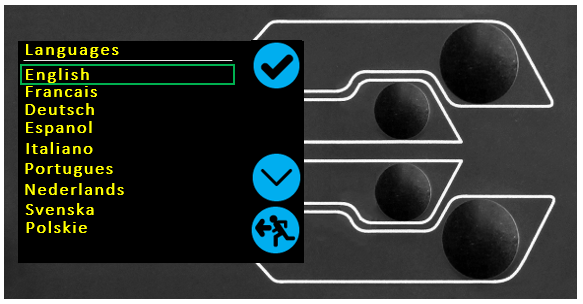
Select your desired language. Upon confirmation, you are returned to the settings menu in the language chosen.
7.6 Information
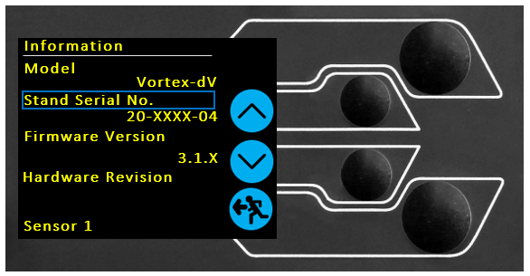
This screen is used to display vital information relating to your Vortex-dV and connected devices. Here you can see hardware and firmware properties.
8 Interlock Guarding Overview
8.1 Operating a Vortex-dV Test Stand Without a Guard Fitted
Voretx-dV test stands supplied (from May 2020), can be operated 'normally' without a supplied guard, for applications that do not warrant a guard to be used.
The stands have an 'Override' feature that allows an interlock override plug (part no. 351-102), supplied as an accessory to be fitted, that enables the use of the stand without a guard fitted. This plug will be supplied in the accessories and must be fitted to use the stand in normal operation.
8.2 Operating a Vortex-dV Test Stand With an Interlocked Guard
Mecmesin interlocked guarding is fitted with a cable and plug from the guard, that must be fitted to the rear of the stand panel 'Interlock' connection, in place of the removed override plug.
When a guard is fitted and connected to the Vortex-dV, there is no need for any menu updates or user interaction to make it functional. The stand will have certain operations and user status warnings when the guard is opened and closed.
8.3 Guard Closed
With the guard door closed, normal menu displays and operations will be seen:
8.4 Guard Opened
8.4.1 With a Test Running
The guard door should never be opened whilst a test is running. Extremely high forces and energy can be present in the machine, grips or sample under test and personal injury or damage can occur.
Allow the machine to complete the test sequence or stop the machine manually and safely remove any residual loading before attempting to open the guard and access the machine, grips or sample under test.
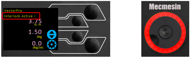
8.4.2 Vortex-dV Without PC Control
When running a Vortex-dV standalone without VectorPro Lite software control, opening the guard will result in a test being aborted and the 'Interlock Active !' status message on the front panel display:
8.4.3 Vortex-dV With VectorPro Lite Control
When controlling the Vortex-dV test stand with VectorPro Lite software functionality, the test stand front panel will behave with same actions as above.
The software will be aborted and the current test will not be recorded or stored. The software screen will briefly show the message shown below to indicate the guard had been opened during a test:

9 Specification
| Vortex-dV | ||||||
|---|---|---|---|---|---|---|
| Rated Capacity | N.m | 0 - 1.5 | 0 - 3.0 | 0 - 6.0 | 0 - 10.0 | |
| kgf.cm | 0 - 15 | 0 - 30 | 0 - 60 | 0 - 100 | ||
| lbf.in | 0 - 13 | 0 - 26 | 0 - 52 | 0 - 90 | ||
| Position | ||||||
| Maximum Rotation | 8000 revs | |||||
| Positional Accuracy | 0.2 ° per 36,000 ° | |||||
| Positional Resolution | 0.1 ° (0.001 rev) | |||||
| Speed | ||||||
| Speed Range | rev/min | 0.1 to 30 | ||||
| Speed Accuracy | At Steady State | ±1% of indicated speed | ||||
| Speed Resolution | 0.001 rev/min | |||||
| Maximum Number of Cycles Per Test | 8000 | |||||
| Dimensions | ||||||
| Height | 781 mm (30.7 ") | |||||
| Width | 390 mm (13.4 ") | |||||
| Maximum travel of adjustable transducer carriage | 182 mm (7.2 ") | |||||
| Maximum Headroom | 505mm (19.9") [448 mm (17.6")] ** | |||||
| Weight | 19.5 kg (48 lb) | |||||
| Electrical Supply | ||||||
| Voltage | 230 V AC 50 Hz or 110 V AC 60 Hz | |||||
| Maximum Power Requirement | 100W | |||||
| Torque Measurement | ||||||
| Torque Accuracy | 0.5% of full-scale | |||||
| Torque Units | mN.m, N.m, kgf.cm, lbf.in, ozf.in (as per AFTI units) | |||||
| Environment Specification | ||||||
| Operating Temperature | 10°C – 35°C (50°F – 95°F) | |||||
| Operating Relative Humidity | Normal Industry and laboratory conditions. (30% to 80% non-condensing) | |||||
| Display & Data Output | ||||||
| Front Panel Display Indication | Load / Displacement / Speed | |||||
| Output of Test Results | Stand | Via USB (VectorPro™ Software - PDF, XLXS, CSV, TXT, Email and Images) | ||||
| AFG/AFTI | Via Cable (contact: sales@mecmesin.com) | |||||
** With upper and lower mounting tables fitted
10 Dimensions
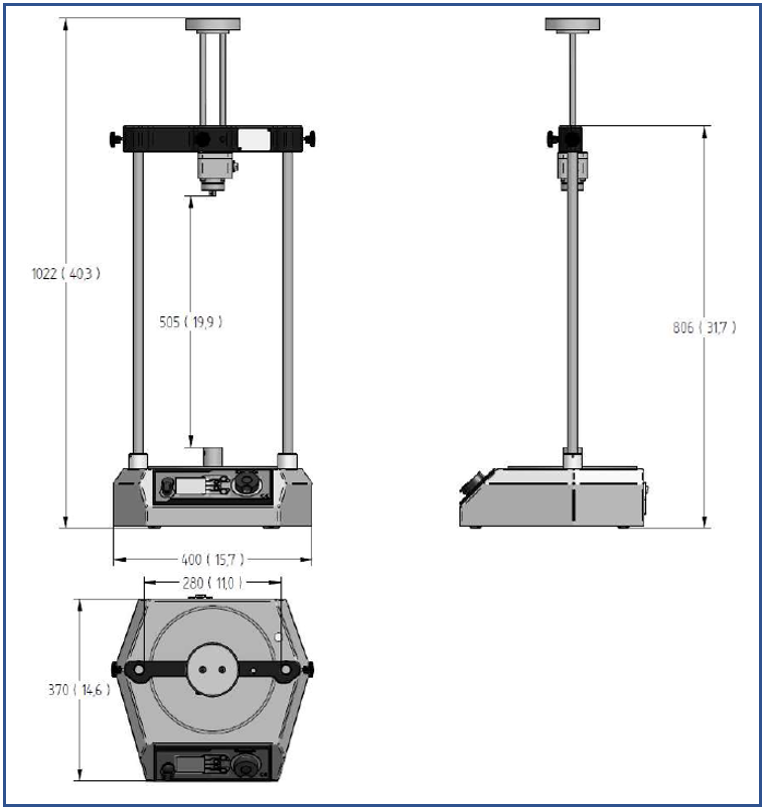
Note: Vortex-dV Dimensions - mm (inch)
11 Declaration of Conformity
For the declaration of conformity for the Vortex-dV, click here.