1 HelixaPro and HelixaPro Touch motorised torque tester operating manual

|
|
2 Introduction
VectorPro™ and VectorPro™ Lite are registered trademarks of PPT Group UK Ltd t/a Mecmesin.
This document refers to Mecmesin HelixaPro test stands operating the latest firmware version.
The following manuals may aid you in the use of your test stand:
- 431-398 - Guide to safe use of mains powered test systems
Covers the intial setup, installation, and safety implications for intended use of any Mecmesin supplied mains-powered equipment.
- 431-955 - VectorPro User Manual - Introduction and initial setup
Covers the initial setup and installation of VectorPro test software, as well as the basics of the software functionality and user manuals. Further guidance relating to other aspects of VectorPro can be accessed through this user manual.
2.1 User manual icons
The icons shown below are used within this operating manual to identify important health and safety information as well as additional installation/operation guidance. Do not proceed until each individual message is read and thoroughly understood.
2.1.1 Warning
2.1.2 Caution
2.1.3 Information
- 1 HelixaPro and HelixaPro Touch motorised torque tester operating manual
- 2 Introduction
- 3 Customer responsibilities
- 4 System summary
- 5 Unpacking and parts supplied
- 6 Initial setup
- 6.1 Unpacking the stand
- 6.2 Mains power supply
- 6.3 Earthing
- 6.4 Fuse specification
- 6.5 Locating the stand
- 6.6 Releasing the crosshead
- 6.7 Fitting the feet/securing lugs
- 6.8 Attaching the Enhanced Torque Sensor (ETS)
- 6.9 Fitting the Touch console (optional)
- 6.10 Connect the test stand to a PC or Touch console
- 6.11 Cable management
- 6.12 Attaching grips and fixtures
- 6.13 Fitting the top mass platen
- 6.14 Counterbalance mechanism
- 6.15 Test stand states
- 7 Front panel controls
- 8 Settings
- 9 Interlock guarding overview
- 10 Specification
- 11 Dimensions
- 12 Declaration of Conformity
3 Customer responsibilities
Before use, it is recommended that all operators of the machinery are given comprehensive training covering the test stand and safety measures.
Preventative safety measures prior to operation, in accordance with all relevant operator manuals, should also be considered.
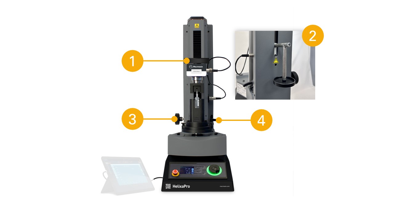
4 System summary
HelixaPro is a motorised torque testing systems, used for torque testing of loads up to 6 N.m.
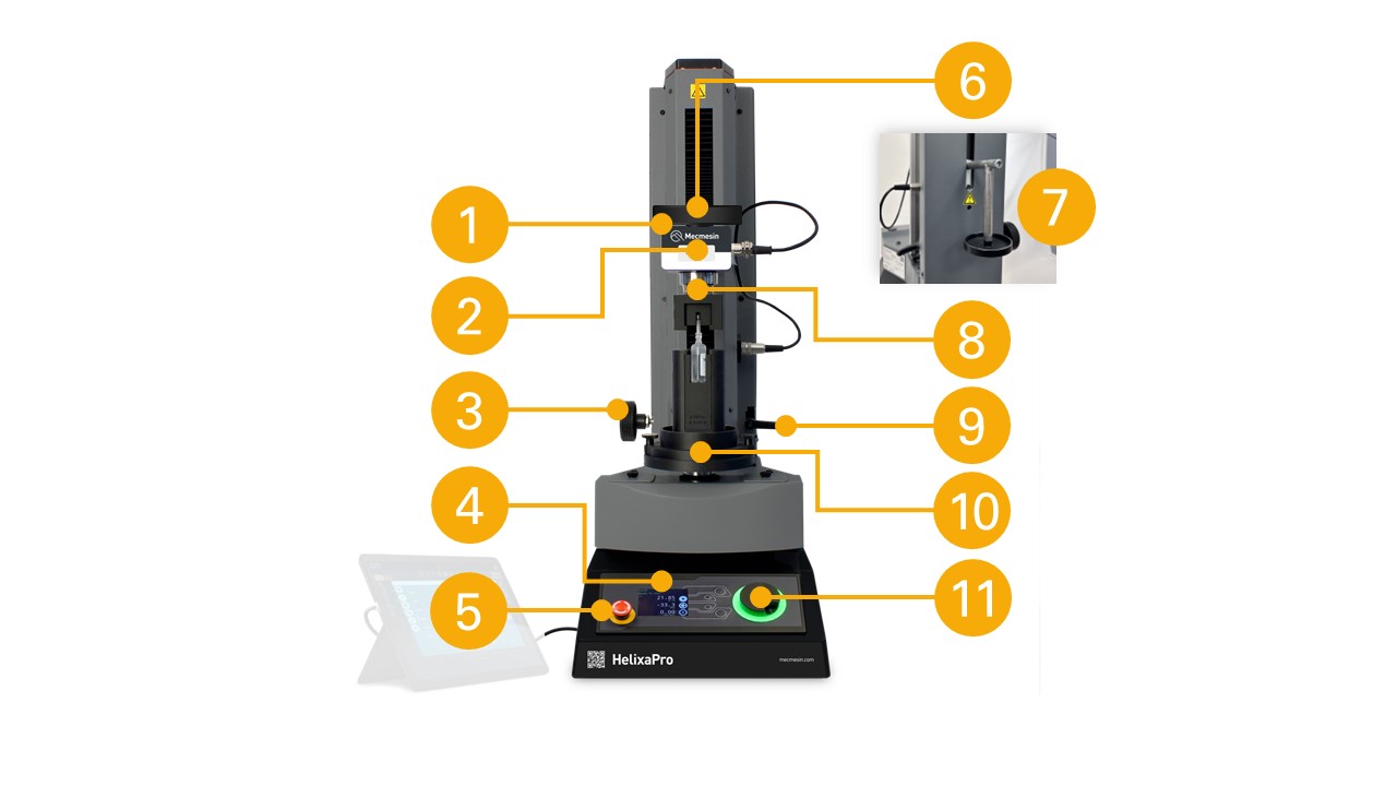
| 1 | Height adjustable crosshead |
| 2 | Enhanced Torque Sensor (ETS) static torque transducer |
| 3 | Crosshead height adjustment dial |
| 4 | Front control panel |
|
5 |
Emergency stop button |
| 6 | Top mass platen for static weights |
| 7 | Counterbalance hanger |
| 8 | Upper fixture (optional - custom sample holder) |
| 9 | Crosshead height securing lever |
| 10 | Lower fixture (optional - custom sample holder) |
| 11 | Multi-function jog wheel controller |
4.1 Comms panel/ports
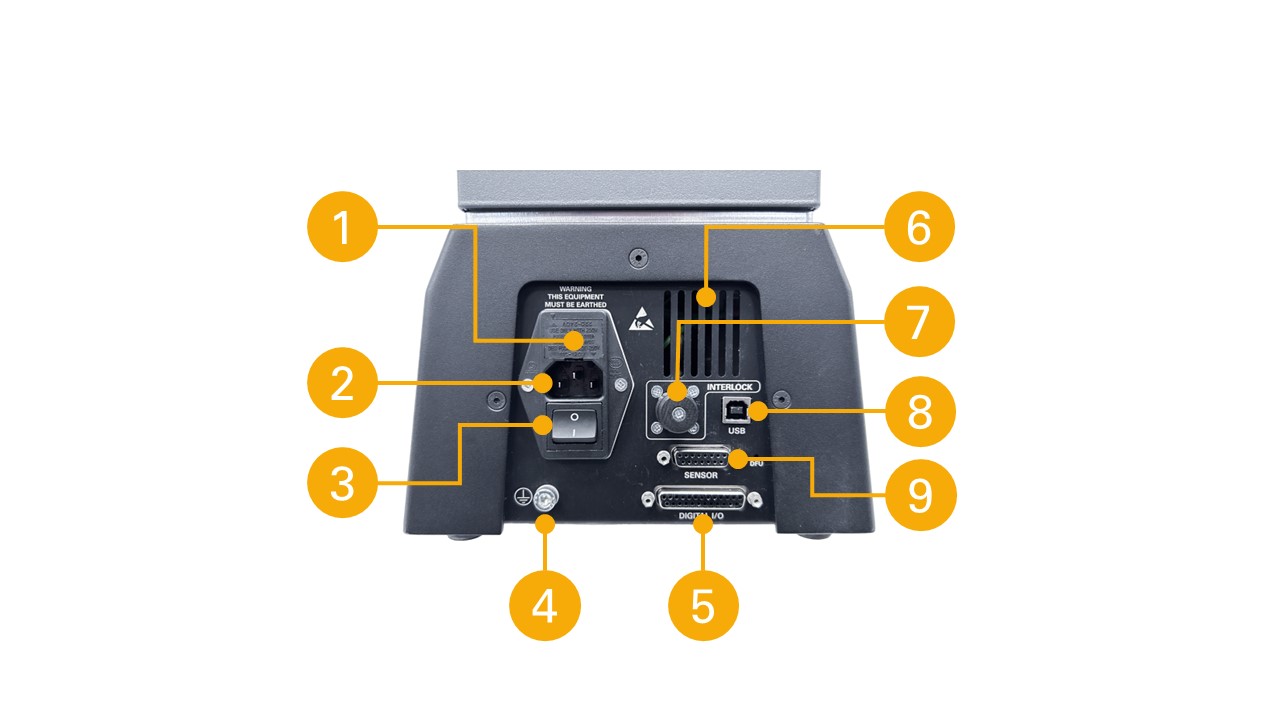
| 1 | Fuse carrier (voltage selector and fuse holder) |
| 2 | Mains power input |
| 3 | Power switch |
| 4 | System earth point (for electrical testing only) |
| 5 | Digital I/O 25-pin comms port |
| 6 | Vent (Do not obstruct) |
| 7 | 'Interlock' connection (interlock override plug shown fitted) |
| 8 | USB-B port (for PC or Touch console control using VectorPro™ software) |
| 9 | Sensor 15-pin comms port |
4.2 System identification plate
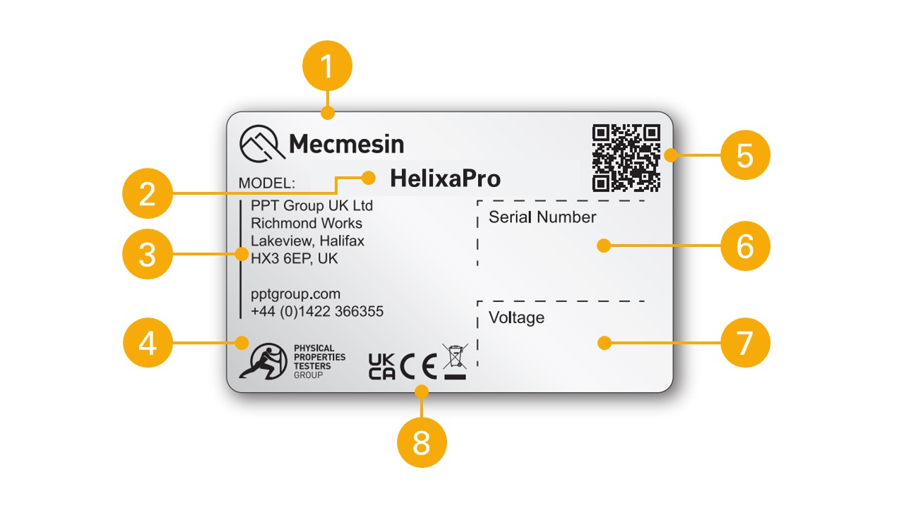
| 1 |
Manufacturer branding |
| 2 | Model name, eg HelixaPro |
| 3 | Manufacturer address |
| 4 | Manufacturer branding |
| 5 | QR code - calibration information |
| 6 | Serial number, eg 24-1005-03 |
| 7 | Voltage information |
| 8 | Conformity markings |
5 Unpacking and parts supplied
5.1 Inspection and unpacking
If any damage is discovered, do not proceed with the installation and contact your local supplier immediately who will decide the most appropriate action and rectify the situation as quickly as possible.
Before installing or operating the HelixaPro system ensure that no visible damage has occurred during the shipping of the device
5.2 Packaging
We strongly recommend that the packaging is retained, as this can be useful if the machine needs to be returned for calibration or shipped to another location.
Parts supplied with the test stand, details the parts that should be included with your test stand. Please contact Mecmesin or your authorised distributor if any items are missing or damaged.
5.3 Moving the test stand
5.4 Parts supplied
Please see the table below for the list of parts supplied with the HelixaPro test stand.
| Item | Quantity |
|---|---|
| HelixaPro test stand | 1 |
| Interchangeable Enhanced Torque Sensor (ETS) | (depd on order) |
| Enhanced Torque Sensor (ETS) dovetail bracket and screws kit (910-432) for HelixaPro | 1 |
| HelixaPro Touch console and test stand fixing bracket (optional) | (optional) |
| 2 metre USB-A to USB-B data cable | 1 |
| M2 hex key | 1 |
| Hex key set (2.5 mm, 3 mm, 4 mm, 5mm) | 1 |
| Mains cable pack (for UK, Europe, and USA) | 1 |
| Top mass platen and fixings | 1 |
| Balance hanger (for external weights/counter-balance) | 1 |
| Alignment tool | 1 |
| Rubber feet | 4 |
| Bench-securing lugs | 4 |
| Attachment screws (for rubber feet or bench-securing lugs) | 4 |
| VectorPro software key | 1 |
| Document: A Guide to Safe Use of Mecmesin Mains Powered Test Systems | 1 |
| Online Manual Information Guide | 1 |
5.5 Accessories
For a full range of accessories, please go to the Mecmesin website (www.mecmesin.com) or contact your local distributor.
6 Initial setup
6.1 Unpacking the stand
If any damage is discovered, do not proceed with the installation and contact your local supplier immediately who will decide the most appropriate action and rectify the situation as quickly as possible.
Before installing or operating the HelixaPro system ensure that no visible damage has occurred during the shipping of the device.
We recommend that the packaging is retained for future use, such as returning the stand for calibration.
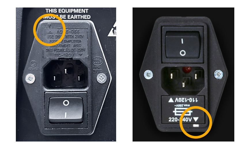
6.2 Mains power supply
HelixaPro test stands can be used on 110–120 or 220–240 V AC, 50-60 Hz supplies. The rear fuse carrier is set for your local requirement but is reversible. Should you replace a fuse, ensure the correct local voltage is selected.
The voltage that is selected is indicated by which the arrow is pointing to the white line, or where the two arrows align, as highlighted below. The power inlet is inverted for some test stands.
6.3 Earthing
HelixaPro test stands must be earthed. Under normal circumstances, this is done using the supplied mains power cable and most industrial mains power outlets. Please consult a qualified electrician if you are unsure of your mains power supply/outlet.
The system earth point at the rear of the test stand is solely for verifying the stand's earthing. It is not a substitute method of earthing for power supplies that are not earthed.
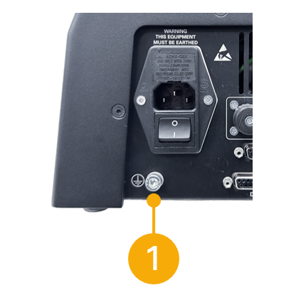
| 1 | System earth point (for verification only) |
6.4 Fuse specification
A HelixaPro test stand uses two 2A - Time-delay (T), 5 x 20mm fuses. If replacing a blown fuse only replace the fuse on the active side of the inlet filter with the fuse specified above, or equivalent.
If you are in doubt, please contact your local Mecmesin support agent for more information.
6.5 Locating the stand
The test stand should be positioned on a suitable, level, stable work surface that can support the weight of the test stand (see specification table).
6.5.1 Ventilation
To prevent overheating, ensure that all ventilation vents on the HelixaPro test stand are free from obstruction.
6.5.2 Enviroment
The HelixaPro should only ever be installed in suitable environmental conditions. The operating temperature and humidity should be within the range given in the specification table.
6.6 Releasing the crosshead
For safety during transit the integrated counterbalance weights are secured internally (see section 'Securing the counterbalance weights' before transporting your test stand).
Ensure the securing lever to the right of the column is locked to prevent movement. Using a 4 mm hex key, as below, loosen the grew screw through the hole in the counterweights, visible at the base of the central slot.
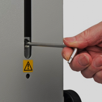
Release the securing lever to the right of the column by a half-turn anti-clockwise. The crosshead can now be raised and lowered manually or with the height-adjustment knob to the left of the column.
Secure the crosshead position with the securing lever to the right of the column by a half-turn clockwise.
6.7 Fitting the feet/securing lugs
Do not try to lift heavy loads unaided. The unpackaged weight of the test stand is listed in the specification table.
The HelixaPro is supplied with rubber feet as standard or with bench securing lugs (optional). As a free-standing unit HelixaPro conforms to BS EN 61010-1:2010 section 7.4(a) requirements for stability.
If you will require the Touch console to be mounted higher than the mid-point of the stand column, or you are going to use additional weights in the top mass platen and/or the rear counterbalance hanger, then you will need to fit the four bench securing lugs for stability and safety.
Handle the test stand by its base and column only. Do not hold it by the crosshead or drive spindle.


Carefully, lay the stand on its back, and fit the four rubber feet (or bench securing lugs) to the bottom of the stand as shown.
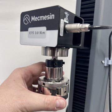
6.8 Attaching the Enhanced Torque Sensor (ETS)
The Enhanced Torque Sensor (ETS) attaches to the crosshead using a dovetail bracket.
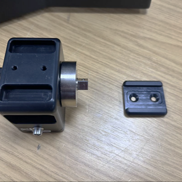
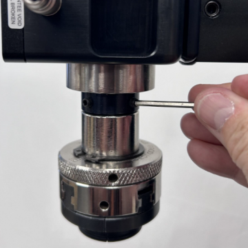
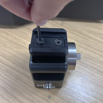 Attach the ETS dovetail bracket to the back of the sensor, using the screws provided in the kit (910-432) and a 3mm hex key.
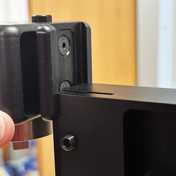
 Slide the ETS down onto the dovetail bracket at the front of the crosshead.
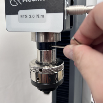
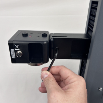 Slide it fully downwards against the stop and tighten the securing screw using a 4mm hex key. Do not over-tighten the securing screw.
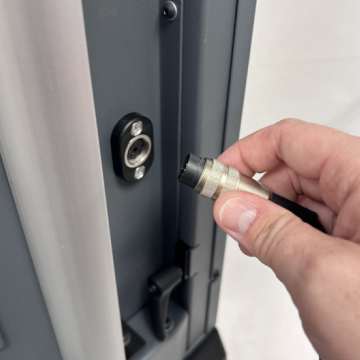 Align the electrical connector of the ETS cable with the socket on the test stand. Gently push the connector to locate, then tighten the knurled locking ring to secure it.
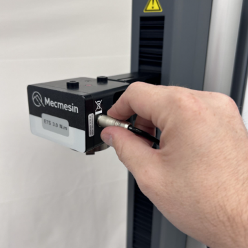 Align the electrical connector of the ETS cable with the socket on the sensor. Gently push the connector to locate.
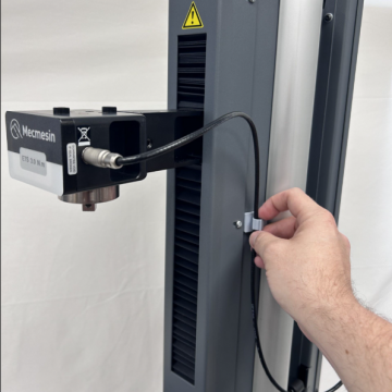 Secure the ETS cable using the clip to the right of the column. Adjust the cable so that there is no tension through the vertical travel of the crosshead and fasten the clip.
You can change ETS, disconnecting one sensor and fitting another, by reversing and repeating the steps above.
6.9 Fitting the Touch console (optional)
The Touch console and support arm can be fitted to the right-hand of the test stand, but it is important to ensure that any cables from the test stand to the console are clear of any moving parts, to prevent any unnecessary kinking.
The fixing bracket can be easily fitted, adjusted or removed without any additional tools.
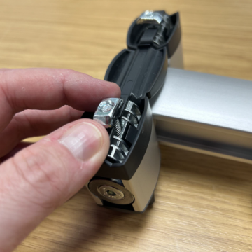
 Attach the T-Slot nuts to the bolts of the support arm. The nuts should be only partially threaded on the bolt, remaining loose, and aligned vertically (as pictured).
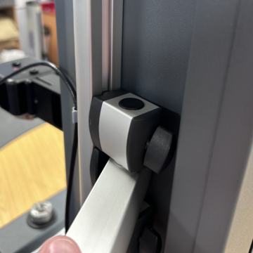
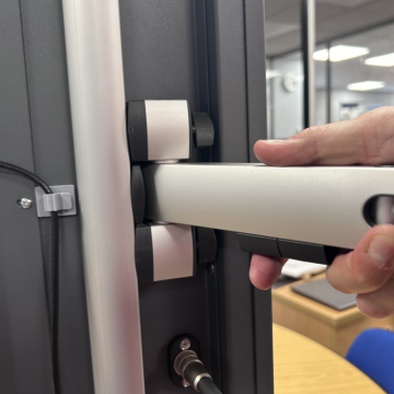 With the T-Slot nuts aligned, insert into the T-Slot rail to the side of the test stand. It is recommended, for weight distribution, to mount the arm at the mid-point of the rail.
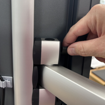 Tighten both upper and lower thumbscrews slowly, ensuring that the nuts have rotated one quarter-turn, for a secure grip in the rail.
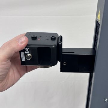
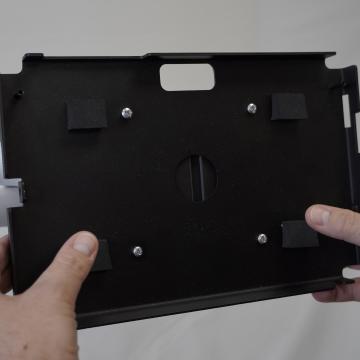 With the arm secured, attach the console holder back plate to the support arm console bracket using the four crosshead screws provided, then insert the Touch console.
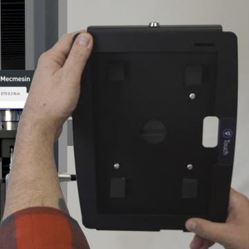 Ensure the console holder front plate is unlocked using the key. Attach it to the back plate and then lock the front plate to secure your console. Adjust the angle of the arm and the orientation of the console as needed. Finally, tighten each hex screw on the support arm joints and ball-joint to secure the desired position.
6.10 Connect the test stand to a PC or Touch console
VectorPro must be installed on the assigned PC (or console) before connecting the test stand to that computer.
To use VectorPro software, you must install the software before connecting your test stand to your PC (or console).
Using the provided data cable, insert the USB-B connector into the USB-B port on the rear of the test stand and the USB-A connector into an available USB-A port on your PC (or console).
6.11 Cable management
Ensure there are no trailing cables that could interfere with the test stand controls or the emergency stop button. All cables should be clear of any moving components.
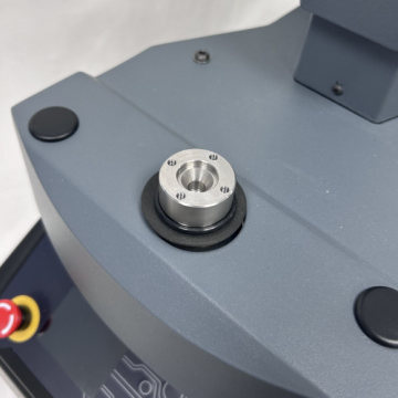
6.12 Attaching grips and fixtures
Grips and other fixtures are usually paired, with the lower fixture attached to the main spindle drive, and the other to the Enhanced Torque Sensor (ETS).
Fixtures on the main spindle have a self-centering fitting and four screws. The ETS has a square drive attachment.
6.12.1 Upper fixture
One example of an upper fixture, attached to the sensor's square drive, using a 2.5 mm hex key to tighten and secure the grub screw.
6.12.2 Lower fixture
One example of a lower fixture is the 100 mm diameter lower fixing plate with a diameter capacity of 20 mm to 100 mm. This is fixed to the HelixaPro drive spindle, using a 2.5 mm hex key to secure the four countersunk screws supplied.
A wide range of torque testing fixtures are available, including adjustable saddle plates, extended grips, mandrels, and chucks. Go to the Mecmesin website (www.mecmesin.com) or contact your local distributor for more information.
6.13 Fitting the top mass platen
 Secure the top mass platen to the top of the Enhanced Torque Sensor (ETS) using the two M6 countersunk screws supplied.
6.14 Counterbalance mechanism
The HelixaPro test stand crosshead is counterbalanced by a system of integrated weights. This enables the entire weight of the crosshead, Enhance Torque Sensor (ETS), and fixtures to be finely counterbalanced so that it does not interfere with torque measurements. For example, measuring the torque of a rising screw thread. Alternatively, it can be use to apply a specific downward force during torque testing by adding static weights to the top mass platen.
| 1 | Top mass platen for static weights |
| 2 | Counterbalance hanger |
| 3 | Crosshead height adjustment dial |
| 4 | Crosshead height securing lever |
The crosshead height adjustment dial (3) can be used to raise or lower the crosshead. The crosshead is fixed in place using the crosshead height securing lever (4) .
6.14.1 Integrated counterweights
The integrated counterweight is made up of two separate weights, that can be connected or separated to apply either the whole weight (2.25 kg) or partial weight (1.5 kg).
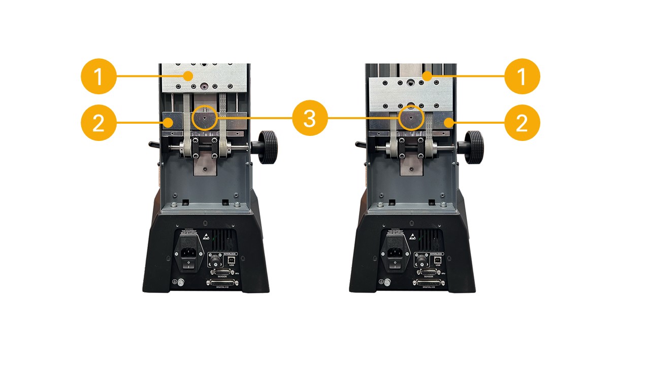
| 1 | Upper counterweight (1.5 kg) |
| 2 | Lower counterweight (0.75 kg) |
| 3 | Counterweight connecting screw |
The image above shows the integrated counterweights (rear cover removed). The left image shows the partial counterweight (1) suspended (1.5 kg in use). The right image shows the whole counterweight (1 & 2) suspended (2.25 kg in use).
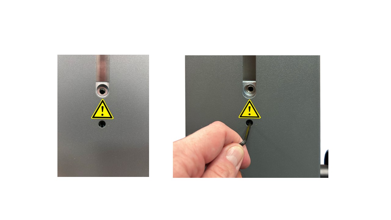
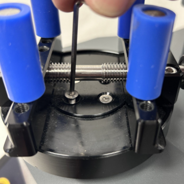
To adjust the counterweights in use, raise the crosshead to its highest position so that the counterweight connecting grub screw is aligned with the hole pictured above. Insert a 2 mm hex key through the hole in the back cover to either:
- Connect the two counterweights by tightening the connecting grub screw. This will apply the whole counterweight of 2.25 kg.
- Disconnect the lower counterweight by loosening the connecting grub screw until you feel the counterweights separate, by pressing down on the crosshead gently at the same time. This will apply the partial counterweight of 1.5 kg.
6.14.2 Counterbalance hanger (for additional weights)
An additional counterbalance hanger can be attached to the rear weight, for additional weights to be suspended. The external counterbalance hanger (3), without static masses, adds an additional 200g when attached.
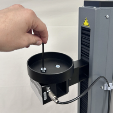
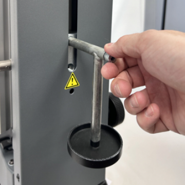 Thread the counterbalance hanger screw into the upper-most counterweight hole, at the rear of the test stand.
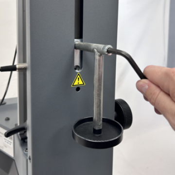 Align the counterbalance hanger vertically and secure the bolt with an 8 mm hex key.
Additional weights/static masses can be suspended on the counterbalance hanger.
6.14.3 Applying top-load
The top mass platen above the moving crosshead/ETS can be used in combination with the counterweights to achieve the required balance (or load) required for testing.
Carefully place weights in the top mass platen. For guidance on using weights for top-load, please contact your local distributor or our technical support team. Excessive weight applied to the top mass platen could damage lower capacity sensors.
The ETS contains sensitive electronics. Dropping weights into the top mass platen may cause damage to the ETS. Handle all components with care to avoid potential harm to the equipment.
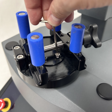
6.14.4 Securing the counterweights
The integrated counterweights must be secured during transit. Failure to do so could lead to personal injury or damage to the equipment.
To secure the counterweights for transporting the test stand, ensure the crosshead height securing lever is engaged to prevent movement, then insert a 4 mm hex key to engage the grub screw through the hole in the weights. The grub screw is visible at the base of the central opening at the rear of the test stand (pictured below).
Secure the crosshead position with the securing lever to the right of the column by a half-turn clockwise.
6.15 Test stand states
The test stand can be in one of five states:
- Test readiness - Ready to start, or complete.
- Testing - Test operation sequence is running.
- Stopped - Test interrupted or emergency stop pressed.
- Jog mode - For jogging or positioning the crosshead manually.
- Settings menu - For adjusting your test stands settings.
In each state, the selector buttons have functions described by the on-screen icons.
7 Front panel controls
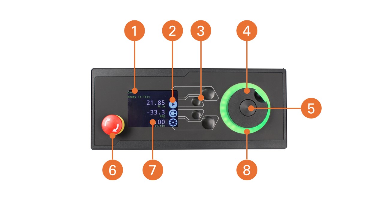
|
1 |
Status messages |
|---|---|
| 2 | Button functions |
| 3 | Multi-function selector buttons |
| 4 | Multi-function scroll wheel |
| 5 | Scroll wheel central button |
| 6 | Emergency Stop |
| 7 | Display |
| 8 | LED status indication dial |
7.1 Emergency Stop button
|
Push to stop the crosshead movement. Rotate the button to release it and resume crosshead control. |
If pressed during a test, remove any residual load using the test stand jog controls before restarting a test
7.2 Multi-function scroll wheel control
7.2.1 Scroll wheel colours
The lights surrounding the wheel illuminate in three colours, indicating the status of the test stand:
| Colour | Status | Indication |
|---|---|---|
|
Green |
Pulsating | Ready to start a test |
| Rotating | Scrolling through menus | |
| Flashing | Test completed | |
|
Amber |
Static | In jog mode menu |
| Rotating | Lower spindle moving | |
|
Red |
Static | Test aborted/limit triggered |
7.2.2 Jog mode
In jog mode, turning the wheel drives the HelixaPro clockwise or anticlockwise, corresponding to the direction of the wheel's turn. This method provides more adjustable control compared to the two fixed-speed jog control buttons (highlighted below).

| 1 | Enter Jog Mode |
|---|---|
| 2 | Jog keys 'Clockwise' and 'Anti-clockwise' |
The scroll wheel can function as a speed controller. The jog buttons move the spindle at preset speeds (configured in the 'Jog Settings' menu, shown below). Rotating the wheel clockwise while holding a jog button increases the speed, and rotating it anticlockwise decreases the speed.
HelixaPro test stands also include a precision jog mode: rotating the scroll wheel while holding the central scroll wheel button moves the test stand at its minimum speed. This is particularly useful when fitting specimens into grips, for example.
7.2.3 Navigation and selection
The scroll wheel and central button can be used to navigate selection menus.

| 1 | Confirm selection - Tick selector button/scroll wheel central button |
| 2 |
Navigate up/down menu options - Up/down selector buttons/scroll wheel |
Once in a selection menu the scroll wheel (2) or up/down keys (2) can cycle through the selections and values.
To confirm a selection, use either the tick selector button (1) or the scroll wheel central button (1).
7.2.4 Central button
The central button is used to confirm a menu selection. It is equivalent to the tick button function.
7.3 Display panel
The display indicates the stand’s status, shows live values, and is used to configure the test stand's settings.
The purpose of the four multi-function buttons is indicated on-screen by adjacent icons. Below is an image illustrating a typical example of the on-screen icons corresponding to the physical buttons.

| 1 | The top icon is 'Confirm' |
| 2 |
The mid-upper icon is 'Up' |
| 3 | 'Menu selection' buttons |
| 4 | The mid-lower icon is 'Down' |
| 5 | The bottom icon is 'Back/Exit' |
7.4 On-screen icons
On-screen icons can vary depending on the current state of the test stand. The functions performed by the physical buttons depend on the menu currently displayed.
Below are reference tables that define the icons in relation to the test stand's state.
7.4.1 Pre-Test
|
Icon |
Action |
 |
Start a test sequence |
 |
Enable jog mode |
 |
Go to settings |
 |
Move to the home position (Set within VectorPro or test start position) |
7.4.2 During a test
|
Icon |
Action |
 |
Pause test - This stops the lower spindle movement, leaving the stand in a state of test readiness. The status message is ‘Interrupted: User’ and the 'Play' and 'Stop' buttons will be displayed. |
 |
Stop test - This will abort the current test running (including the VectorPro software). The status message is 'Test aborted' and the 'Home' and 'Exit' buttons will be displayed. |
 |
Emergency stop button pushed: Message: ‘Emergency Stop!!!’. Release the emergency stop to regain control and remedy the situation before resuming testing. Note there is no on-screen icon for the emergency stop. |
7.4.3 Pause/Stopped
|
Icon |
Action |
|
Continue test sequence. |
|
Stop test - Shown when the Pause button is pressed. This ends the test at this point. |
|
Move to the home position (start position from the beginning of the previous test) -This icon is only visible after pressing the 'Stop' button. |
 |
Exit to the test ready screen, leaving the crosshead in its current position - This icon is only visible after pressing the 'Stop' button. |
7.4.4 Jog mode
|
Icon |
Action |
 |
Zero (tare) all system values. |
 |
Move the lower spindle in a clockwise direction at the set jog speed. |
 |
Move the lower spindle in a anti-clockwise direction at the set jog speed. |
 |
Go back to the previous screen. |
7.4.5 Settings menu
|
Icon |
Action |
 |
Confirm selection (or press the centre scroll wheel button). |
 |
Navigate up a menu selection or value (or turn the wheel clockwise). |
 |
Navigate down a menu selection or value (or turn the wheel anticlockwise). |
|
Go back to the previous screen. |
8 Settings
8.1 Jog settings
Within the jog settings menu, you can configure the jog speed limits while in jog mode. Below is a detailed breakdown of each setting and the options available for each setting.
|
Setting |
Action |
Range |
|
Clockwise speed |
Configure the jog speed in a clockwise direction |
0.1 to 30 rev/min |
|
Anticlockwise speed |
Configure the jog speed in an anticlockwise direction |
0.1 to 30 rev/min |
| Jog timeout period |
Set the timeout (in minutes) that the machine will keep the motor drive engaged, before the motor drive is disabled. The load applied to the torque sensor must reach at least 25% of the sensor capacity before the timeout activation is applied. At the end of the timeout period, the 'Jog Active' menu screen is automatically switched back to the 'Ready to Test' menu screen. For example: |
1 to 59 minutes |
|
Clockwise torque limit |
Configure the clockwise torque limit while in jog mode. |
0 to 125% torque cell capacity |
|
Anticlockwise torque limit |
Configure the anticlockwise torque limit while in jog mode. |
0 to 125% torque cell capacity |
8.2 Units
Within the units menu, you can configure the test stands units for displacement and speed.
|
Setting |
Units available |
|
Angle |
rev, deg |
|
Speed |
rev/min, rev/sec, deg/min, deg/sec |
|
Torque |
N.m, N.cm, mN.m, gf.cm, kgf.cm, kgf.m, lbf.ft, lbf.in, ozf.in |
8.3 Edit test
8.3.1 Cycle (by Angular Displacement)
In a cyclic test, the spindle moves between two reference angles that are relative to tared zero.
|
Setting |
Options |
|
Cycle count |
0-9999 |
|
Clockwise speed |
0-30 rev/min (0 to 180 deg/s) |
|
Anticlockwise speed |
0-30 rev/min (0 to 180 deg/s) |
|
Clockwise angle |
A positive value is clockwise from tared zero and a negative value is below |
|
Anticlockwise angle |
A positive value is clockwise from tared zero and a negative value is below |
| Start direction | Choose whether the test direction is clockwise or anticlockwise |
| Move to start | Select if the test moves to the start position first |
Example
- Clockwise Angle: +1000°
- Anticlockwise Angle -30°
- Initial stroke: Clockwise
- Move to Start: Yes
Unless already at -30° the spindle will first travel to that point. The stand will then move to +1000° from tared zero, followed by a final movement back to -30°.
8.3.1.1
8.3.2 Data capture within VectorPro™
VectorPro manages the test configuration to control test stand operation, ensuring the speed and test orientation match your requirements. VectorPro also provides real time visualisation of results during testing. Data is stored with VectorPro's database for analysis, and can be exported to most popular formats using the built-in reporting templates, such as PDF, XLSX, CSV, TXT, HTML, and many more.
At the end of a test, or in a stopped condition, you may need to move the crosshead to clear a sample, or the drive spindle to remove residual torque.
Never restart a test from a stopped condition with a residual torque, and always Reset the gauge before a subsequent test.
For more information please refer to the VectorPro operating manual (part no. 431-955).
Half Cycle
If the test stand is switched off or loses power during an active test, the drive spindle will stop.
A half-cycle test is to an angular displacement relative to tared zero. A cycle starts when the crosshead is at the first displacement position and ends back at the second position.
|
Setting |
Options |
|
Cycle Count |
0-8000 |
|
Clockwise Speed |
0-30rev/min (0 to 180 deg/s) |
|
Anticlockwise Speed |
0-30rev/min (0 to 180 deg/s) |
|
Clockwise Angle |
A positive value is clockwise from tared zero and a negative value is below |
|
Anticlockwise Angle |
A positive value is clockwise from tared zero and a negative value is below |
| Start Direction | Choose whether the test direction is clockwise or anticlockwise |
| Move to Start | Select if the test moves to the start position first |
Example
- Clockwise Angle: +180°
- Anticlockwise Angle -90°
- Initial stroke: Clockwise
- Move to Start: Yes
Unless already at -90° from tared zero, the spindle will travel to that point and then move to +180° from tared zero, and stop.
8.3.3 Operation sequence and move to start
Operations, such as the half cycle consist of two datum points, a clockwise angle and anticlockwise angle.
For operations with the primary movement being clockwise, the following is true:
- · The ‘Anticlockwise Angle’ is the start position for the test and the ‘Clockwise Angle’ is the finishing position.
For operations with the primary movement being anticlockwise, the following is true:
- The ‘Clockwise Angle’ is the start position for the test and the ‘Anticlockwise Angle’ is the finishing position.
Within the ‘Edit Test’ display on your test stands front panel there is an option called ‘Move to Start’, setting this feature to ‘Yes’ means that the stand always moves to the start position.
In some instances, this means the first direction of movement is opposite to the primary test movement. Jog settings
8.4 PIN code
Within the PIN code menu, it is possible to set a four-digit number that can be used to lock the menu feature of the test stand. Please note once this has been set you cannot access the menu without the PIN, so it is crucial that you keep a record of this safe.
8.5 Languages
Select your desired language.
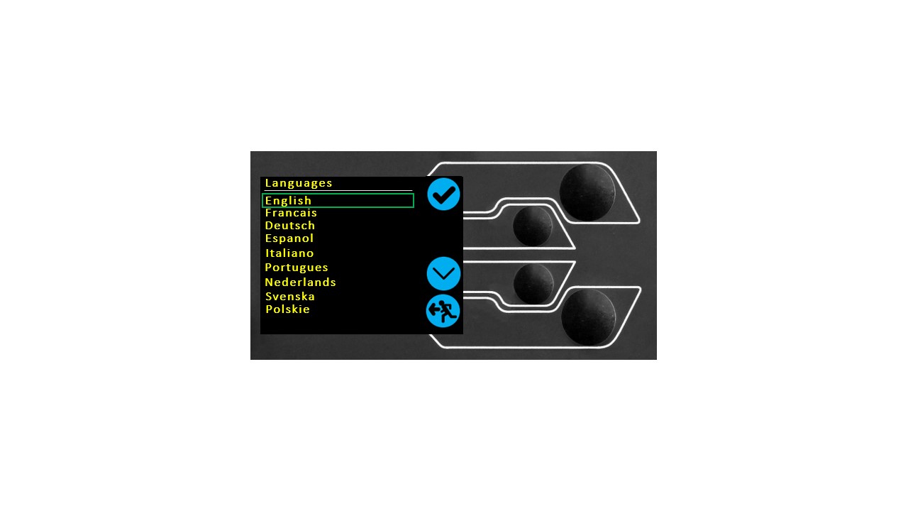
Upon confirmation, you are returned to the settings menu in the language chosen.
8.6 Information
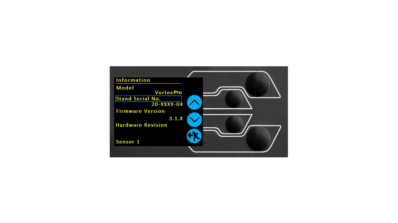
This screen is used to display vital information relating to your HelixaPro and the connected ETS sensor including software, hardware, and firmware properties. You can also review calibration data for the test system.
8.7 Software setup
A VectorPro license is required to run a HelixaPro test stand and VectorPro software.
VectorPro test software is supplied on a USB key or can be downloaded online from: https://downloads.vectorpro.cloud
The software installation file(s) should be copied to a location from where it can be run on the operator's computer. Please do not connect the test stand until the installation has been completed.

Locate the download or installation folder and start the installation by double-clicking the Vector.Installer.exe (executable file).

Once open, click on the 'Install VectorPro' option.

The VectorPro installer will install drivers necessary to complete the installation.

Once the associated drivers have been installed, the VectorPro software installation wizard will launch. Click 'Next' to continue and review the software license agreement.

Before continuing the software installation, it is important that you read, understand and agree to the software license agreement in full. If you do not agree then the software installation will be terminated.
To continue, after agreeing to the license agreement, press the 'Next' button.

Select the installation location and whether the software installs for all users (Everyone) on this computer or the current user only (Just me).
Press 'Next' to continue.

Click 'Next' to confirm installation.

After installation click 'Close'.

Click the 'Tick' button to continue.

You can now choose whether to enable 'Full Screen Mode' for VectorPro.

Finally click the 'Off' button to exit the installer.
8.8 Software data access
Please ensure than all Windows user accounts that launch VectorPro have Admin 'Full Control' access to the following locations:
- Default database location:
C:\ProgramData\Mecmesin\VectorPro\
- Default install location:
C:\Program Files (x86)\Mecmesin\VectorPro\
- Custom database location:
If a custom database location is specified, the Windows user must also have Admin access for this location
If you are unsure of how to perform any of the steps above, please contact your organisation's IT department for assistance.
9 Interlock guarding overview
Appropriate personal protective equipment should be worn and full local risk assessments should have been completed before use. Please refer to the supplementary documentation supplied with the Interlock guarding for full details of safety and operation.
Interlocked guarding for the HelixaPro is supplied as a Product Design Variant (PDV), available as an additional item upon request.
Please contact your local Mecmesin sales representative or authorised distributor for more details.
9.1 Operating test stand without a guard fitted
HelixaPro test stands can be operated without a supplied guard for applications that do not warrant a guard.
Test stands have an 'Override' feature that allows an interlock override plug (Part no. 351-102) supplied as an accessory to be fitted, enabling the use of a test with without a guard fitted. This plug will be supplied in the accessories and must be fitted to use the stand in normal operation.
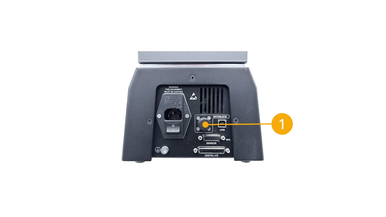
9.2 Operating test stand with an interlocked guard
Mecmesin interlocked guarding is fitted with a cable and plug from the guard, that must be fitted to the rear of the stand panel 'Interlock' connection, in place of the removed override plug.
When a guard is fitted and connected to the HelixaPro there is no need for any menu updates or user interaction to make it functional. The stand will have certain operations and user status warnings when the guard is opened and closed.
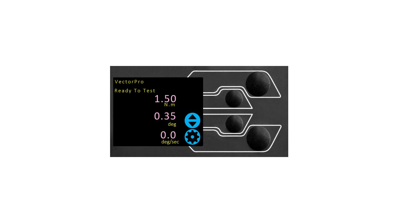
9.3 Guard closed
With the guard door closed, normal menu displays and operations will be seen:
9.4 Guard opened
9.4.1 With a test running
Allow the machine to complete the test sequence or stop the machine manually and safely remove any residual load before attempting to open the guard and access the machine, grips or sample under test.
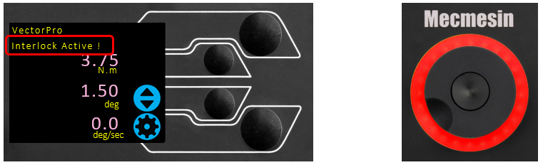
9.4.2 HelixaPro without VectorPro software control
When running a HelixaPro standalone without VectorPro software control, opening the guard will result in a test being aborted and the 'Interlock Active!' status message on the front panel display:
9.4.3 HelixaPro with VectorPro software control
When controlling the HelixaPro test stand with VectorPro test software, the test stand front panel will behave with same actions as above.
The software will be aborted and the current test will not be recorded or stored. The software screen will briefly show the message shown below to indicate the guard had been opened during a test:

10 Specification
| HelixaPro | ||||||||||
|---|---|---|---|---|---|---|---|---|---|---|
| Test stand rated capacity | N.m | 0 - 6 | ||||||||
| kgf.cm | 0 - 60 | |||||||||
| lbf.in | 0 - 52 | |||||||||
| Torque sensor (ETS) capacity | N.m | 0 - 0.1 | 0 - 0.2 | 0 - 0.3 | 0 - 1 | 0 - 1.5 | 0 - 3 | 0 - 6 | ||
| kgf.cm | 0 - 1 | 0 - 2 | 0 - 3 | 0 - 10 | 0 - 15 | 0 - 30 | 0 - 60 | |||
| lbf.in | 0 - 0.9 | 0 - 1.8 | 0 - 2.7 | 0 - 9 | 0 - 13 | 0 - 26 | 0 - 52 | |||
| Position | ||||||||||
| Maximum rotation | 2,999 revs | |||||||||
| Positional accuracy | ±0.2° | |||||||||
| Positional resolution | 0.1° | |||||||||
| Speed | ||||||||||
| Speed range | rev/min | 0.1 to 30 (clockwise or anticlockwise) | ||||||||
| Speed accuracy | At steady state | ±1% of indicated speed | ||||||||
| Speed resolution | 0.001 rev/min | |||||||||
| Maximum number of cycles per test | 8000 | |||||||||
| Dimensions | ||||||||||
| Height | 750 mm | |||||||||
| Width | 290 mm (586 mm inc. console) | |||||||||
| Depth | 414 mm (500 mm with external counterbalance hanger) |
|||||||||
| Crosshead stroke | 244 mm | |||||||||
| Maximum headroom | 292 mm (without fixtures) | |||||||||
| Throat depth | 112 mm | |||||||||
| Weight | 33 kg (35 kg inc. console) | |||||||||
| Static weights | ||||||||||
| Axial load via masses on platen | 60 N (max with a 6 Nm sensor) |
|||||||||
| Axial load via masses on external counterbalance hanger | 40 N | |||||||||
| Electrical supply | ||||||||||
| Voltage | 230 V AC 50 Hz or 110 V AC 60 Hz | |||||||||
| Maximum power requirement | 120W | |||||||||
| Torque measurement | ||||||||||
| Torque accuracy | 0.5% of full-scale | |||||||||
| Torque units | mN.m, N.cm, N.m, kgf.cm, gf.cm, ozf.in, lbf.in, lbf.ft | |||||||||
| Sampling rate | Selectable: 10 - 1,000 Hz | |||||||||
| Environment specification | ||||||||||
| Operating temperature | 10°C - 35°C | |||||||||
| Operating relative humidity | Normal Industry and laboratory conditions (30 - 80%), non-condensing | |||||||||
| Display and data output | ||||||||||
| Front panel display indication | Load / Displacement / Speed | |||||||||
| Output of test results | Stand | PDF, XLSX, HTML, CSV, TXT, email and image files can all be exported from VectorPro software | ||||||||
** With upper and lower mounting tables fitted
Please note that the specifications and features described in this manual are subject to change without notice. Mecmesin reserves the right to make improvements or modifications to the product at any time, which may not be reflected in this document. For the most up-to-date information, please refer to our website or contact your local Mecmesin representative.
11 Dimensions
Front view:

Side view:

Rear view:

Note: HelixaPro dimensions are approximate and in millimeters (mm).
12 Declaration of Conformity

For the full declaration of conformity certificate for the HelixaPro, click here.