1 OmniTest Single Column Test Systems User Manual
|
431-959 July 2023 |
2 Introduction
OmniTest™ and VectorPro™ are both registered trademarks of Mecmesin Ltd.
This reference manual covers the operation of Mk1 and Mk2 OmniTest 0.5, OmniTest 1.0, OmniTest 2.5, OmniTest 5 and OmniTest 7.5 force test systems, intended for use with Mecmesin enhanced load sensors, extensometer devices and other Mecmesin accessories. This manual may also refer to these devices as ‘Single Column’.
Force sensors used by the OmniTest test stands are called ‘Enhanced Load Sensors’ and they are abbreviated to the term ‘ELS’ in this manual.
The following manuals may aid you in the use of your test stand:
|
|
|
Mecmesin Long Travel Extensometer Installation Guide (431-969) |
 |
 |
VectorPro™ User Manual - Introduction and Initial Setup (431-955) |
2.1 User Manual Icons
Throughout this manual, the icons shown below are used to identify important health and safety information as well as additional installation/operation guidance. Do not proceed until each individual message is read and thoroughly understood.
2.1.1 Warning
2.1.2 Caution
2.1.3 Information
- 1 OmniTest Single Column Test Systems User Manual
- 2 Introduction
- 3 System Diagrams
- 4 Unpacking and Parts Supplied
- 5 Initial Setup
- 6 Enhanced Load Sensor (ELS) Setup
- 7 Front Panel Controls
- 8 OmniTest Single Column Settings
- 9 Automatic ELS Firmware Update
- 10 OmniTest Series Specification
- 11 OmniTest 0.5 Dimensions
- 12 OmniTest 1.0 Dimensions
- 13 Omnitest 2.5 Dimensions
- 14 OmniTest 5 Dimensions
- 15 OmniTest 7.5 Dimensions
- 16 Declaration of Conformity
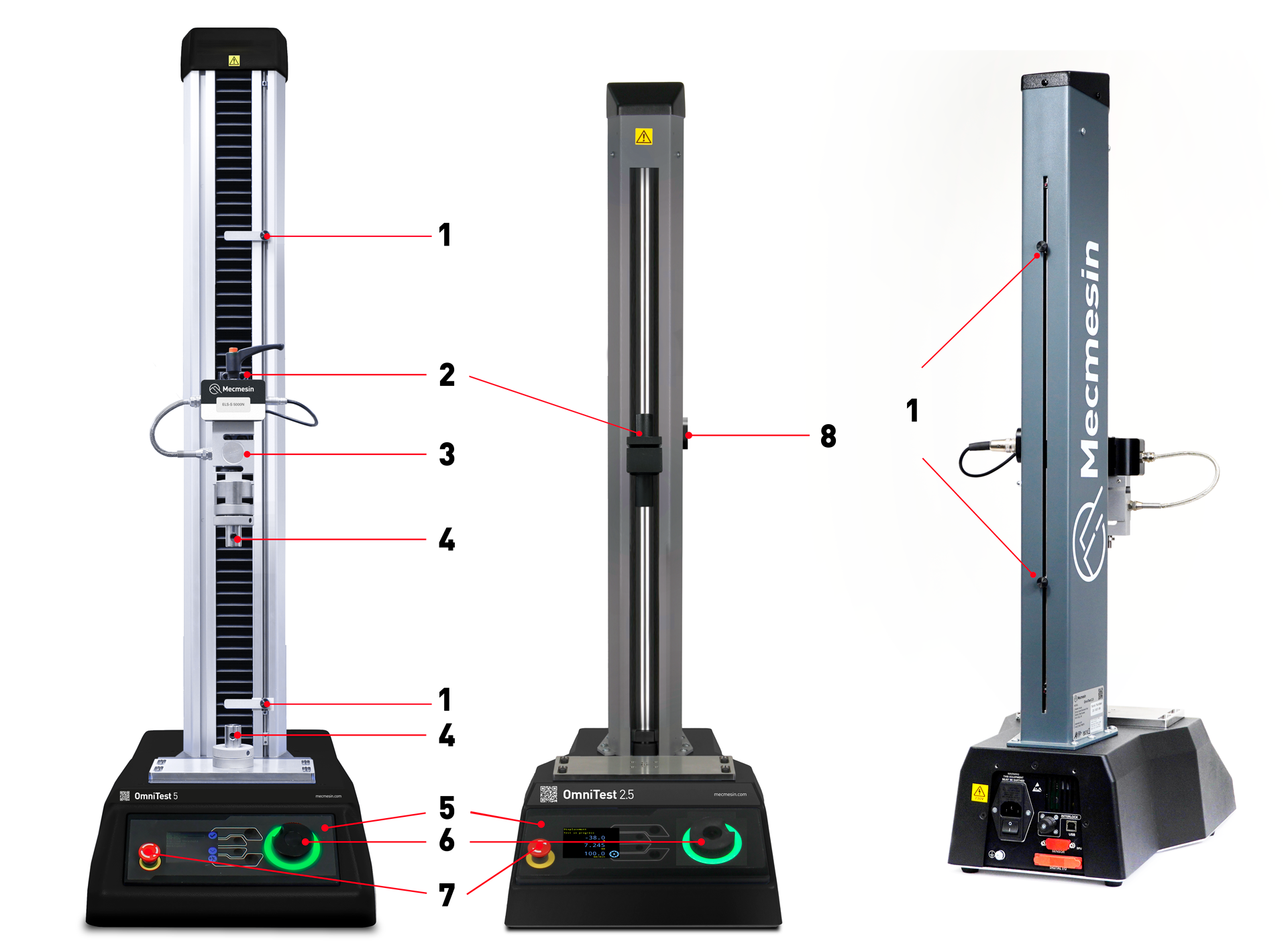
3 System Diagrams
|
1 |
Upper and lower limit switch settings |
|---|---|
|
2 |
Moving crosshead mounting |
|
3 |
ELS (Enhanced Load Sensor) ELS- S series shown fitted with dovetail mounting system |
|
4 |
Upper and lower QC type ‘C’ grip mounting |
|
5 |
Front control panel and display |
|
6 |
Multi-function scroll wheel |
|
7 |
Emergency-stop switch |
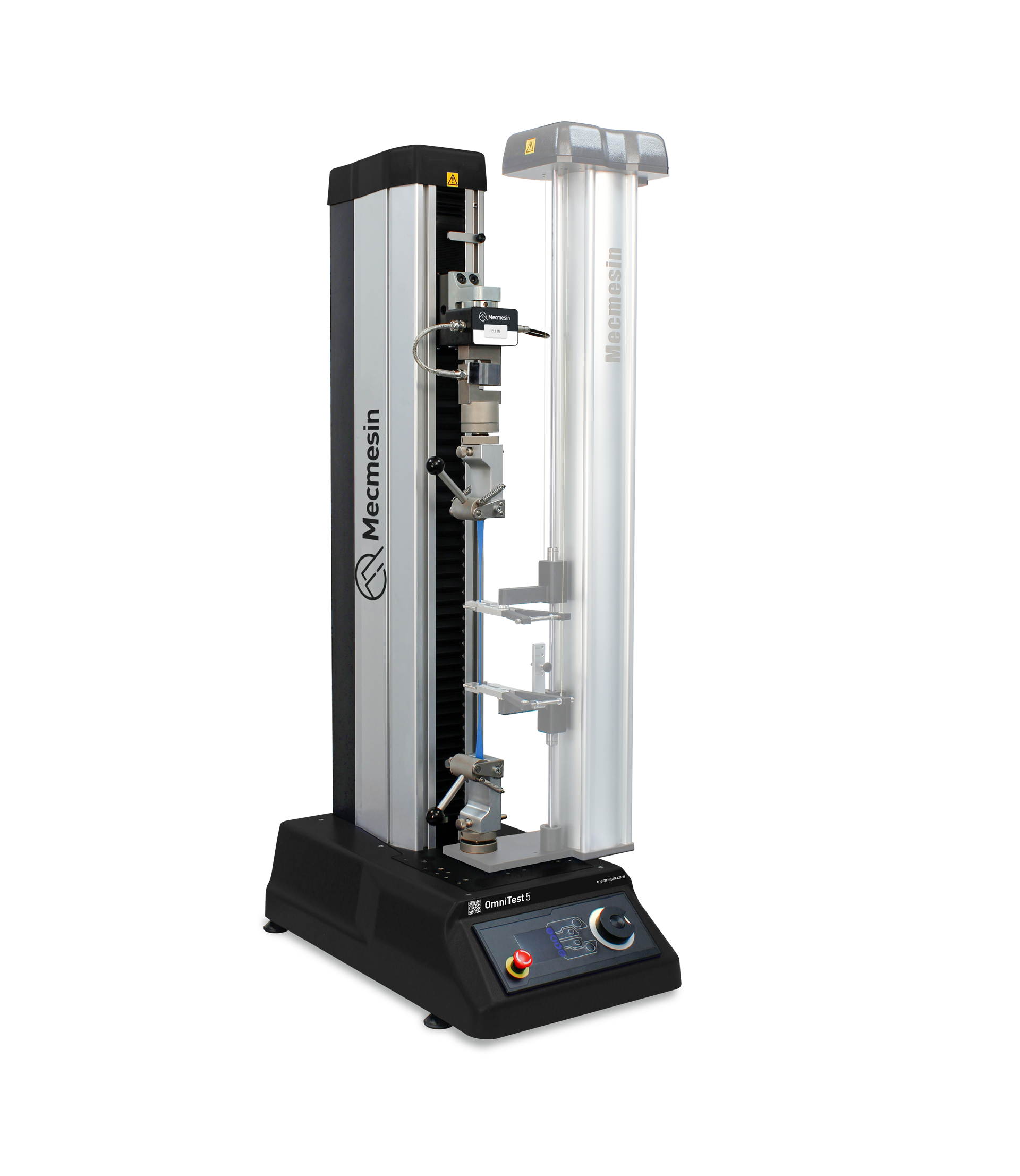
3.1 OmniTest 0.5, 1.0, 2.5 and 5 System Details
The OmniTest 0.5 has a maximum force capacity up to 500N (112.4 lbf).
The OmniTest 1.0 has a maximum force capacity up to 1000N (225 lbf).
The OmniTest 2.5 has a maximum force capacity up to 2500N (562 lbf).
The OmniTest 5 test stand has a maximum force capacity up to 5000N (1124 lbf).
 Dovetail fitting on an OmniTest 5
The dovetail fitting will accommodate both the ELS series and ELS ‘S’ series load cells. For more information relating to individual ELS types please see the following section 'Mounting an ELS to an OmniTest 5'
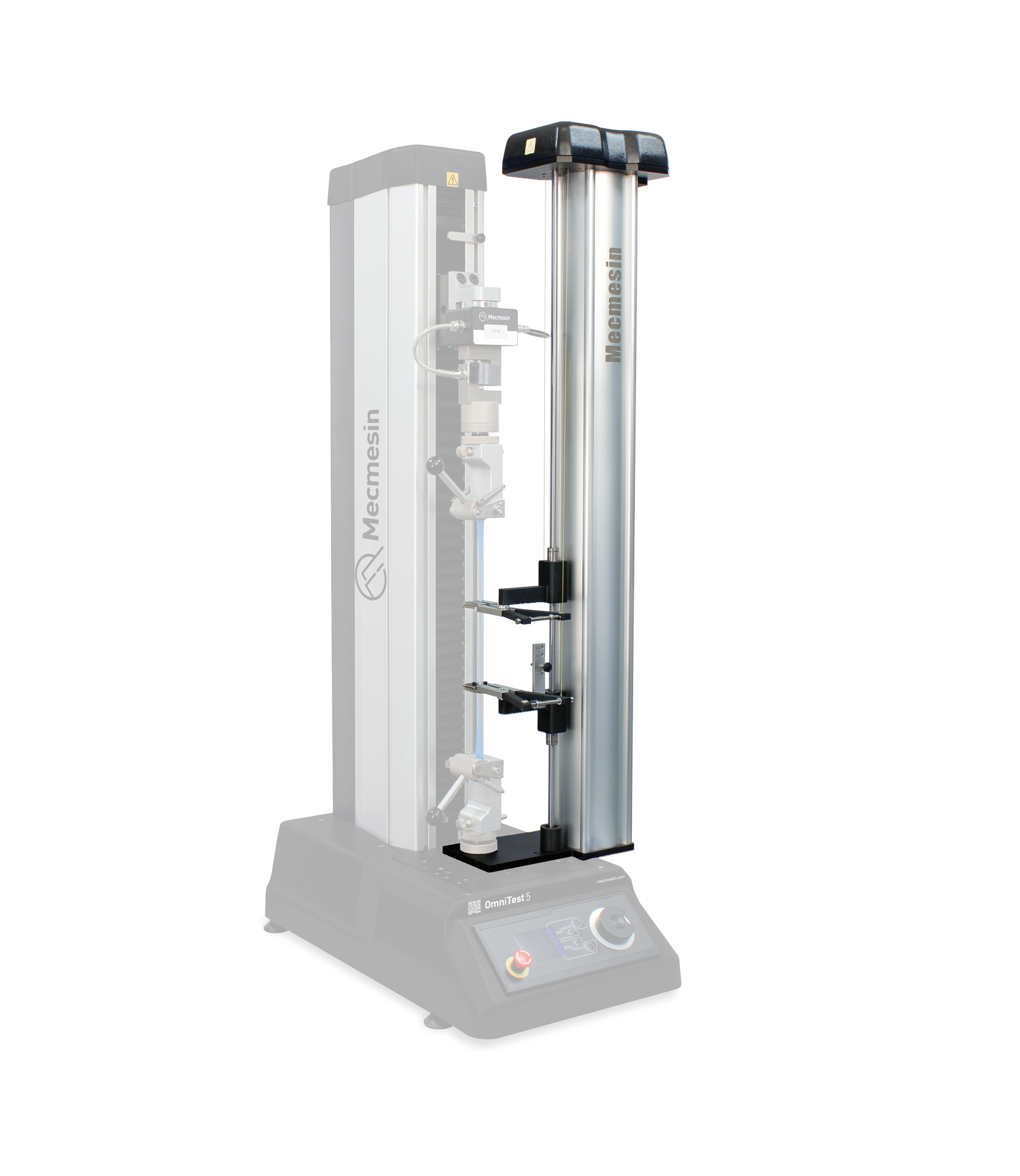
3.2 OmniTest 7.5 System Details
The OmniTest 7.5 machine has the same functional operation and user settings as the OmniTest 5 shown in the System Diagrams. There are operational dimension differences detailed in the specification and technical drawing. Please refer to the OmniTest 5 and OmniTest 7.5 technical drawings or OmniTest 5 and OmniTest 7.5 specification tables for more information.
The mounting bracket is fixed at a right-angle and allows direct axial mounting of the load cell, through its housing via a reinforced connection.

|
1 |
7.5kN Crosshead adaptor |
|---|---|
|
2 |
ELS-T Series load cell |
3.3 Rear Connectors Panel
3.3.1 OmniTest 5 and 7.5
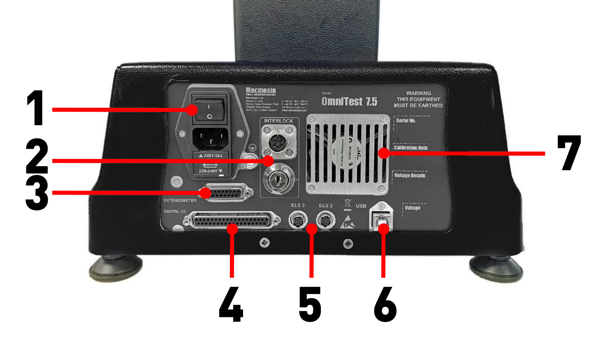
| 1 | Inlet Mains filter and On/Off switch |
|---|---|
|
2 |
Guard Interlock connector and Override Key |
|
3 |
Extensometer input port |
|
4 |
Digital I/O port (not currently implemented) |
|
5 |
Additional ELS input ports |
|
6 |
USB-B communication port (for use with VectorPro™ software) |
|
7 |
System extraction fan (Do not obstruct!) |
3.3.2 OmniTest 0.5, 1 and 2.5
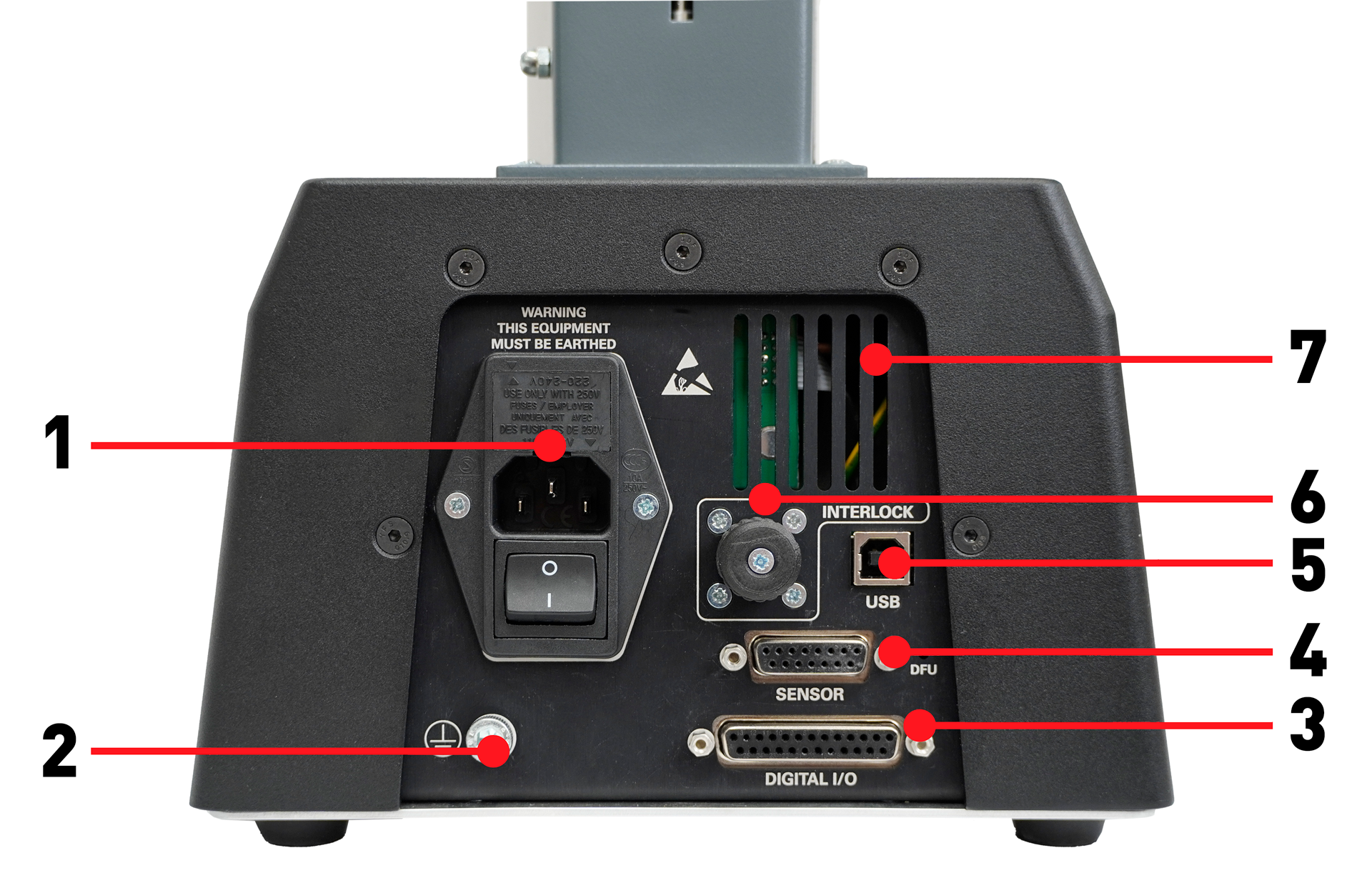
| 1 | Mains connection and Inlet Filter (contains voltage selector and fuse holder) |
|---|---|
| 2 | System earth point |
| 3 | Digital I/O port (not currently implemented) |
| 4 | Sensor input port (currently for ELS 2 + 3 or AFG) |
| 5 | USB connection for PC control using VectorPro™ software |
| 6 | Interlock connection port |
4 Unpacking and Parts Supplied
4.1 Inspection and Unpacking
Before installing or operating the OmniTest system ensure that no visible damage has occurred during the shipping of the device.
4.2 Packaging
We strongly recommend that the packaging is retained, as this can be useful if the machine needs to be returned for calibration or shipped to another location.
4.3 Moving the Test Stand
4.4 Parts Supplied
Please see the table below for the list of the parts supplied with the OmniTest system:
| Item | Quantity |
|---|---|
| OmniTest 0.5, 1.0, 2.5, 5 or 7.5 test stand | 1 |
| Mains cable | 1 |
| Document: A Guide To Safe Use Of Mecmesin Mains Powered Test Systems | 1 |
| Online manual information card | 1 |
| OmniTest Foot Clamps | 4 |
4.5 Accessories Available
For a full range of enhanced load sensors (ELS), extensometers and accessories, please visit the online Mecmesin Accessory Catalogue or contact your local distributor.
- For connection between the test stand and computer, a Mecmesin supplied 2m USB B to USB A communications cable is required (part no. 351-093).
5 Initial Setup
5.1 Mains Power Supply
OmniTest devices can be used on 110–120V ac, or 220–240V ac, 50-60 Hz supplies. The rear fuse carrier should be supplied set for your local mains power requirement, but is reversible. Should the fuse be replaced, the correct local voltage must be selected.
The voltage that is selected is indicated by which arrow is pointing to the white line located at the bottom of the device. This is illustrated in the image below, shown within the red circle.
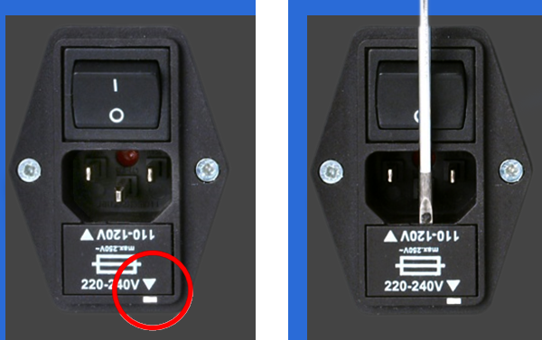
The fuse holder can be ejected using a small flat-blades screwdriver and applying gentle pressure to the upper edge of the fuse holder carriage as indicated below in the right-hand image.
5.1.1 Fuse Specification
The fuse rating depends on the test stands inlet voltage:
- For test stands set to 220-240V ac: 3.15A - Cooper Bussmann S505 Ceramic Cartridge Fuse, Speed T, 5 x 20mm – Or Equivalent.
- For test stands set to 110-120V ac: 5A - Cooper Bussmann S505 Ceramic Cartridge Fuse, Speed T, 5 x 20mm – Or Equivalent.
If replacing a blown fuse only, replace the fuse on the active side of the inlet filter with the fuse specified above, or equivalent. Fuses must be fitted to the correct side of the inlet filter.
Incorrectly fitted fuses could cause serious damage to your machine. If you are in doubt please contact your local Mecmesin support agent for more information.
5.2 Fitting Foot Clamps
OmniTest test systems are supplied with four-foot clamps (Part no. 409-027), these can be used to secure the test stand to a suitable work surface.
This prevents the stand from toppling or sliding. It is recommended that the foot clamps are used, especially for systems with MLTE (Mecmesin Long Travel Extensometer) devices fitted.
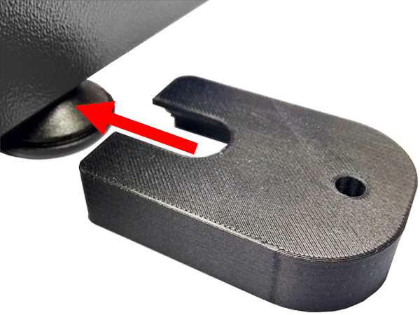
To secure the OmniTest test stand, first slide the foot clamp over the feet located on the base of the stand, as pictured above.
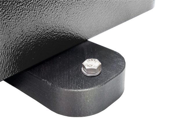
Then, thread the supplied screw through the foot clamp and the work surface. Using the supplied nut and washer secure the foot clamp below the work surface.
5.3 Connecting the OmniTest Stand to a PC
To connect the OmniTest test stand to VectorPro software, connect the USB B port to a PC using cable part no. 351-093.
Important! Please install VectorPro software on your desired PC before connecting the test stand to your PC. For more information please refer to the Installing VectorPro section from the VectorPro Introduction and Initial Setup User Manual.
5.3.1 Cable Management
5.4 Updating Stand Firmware: Vector Instrument Programmer (VIP)
From time to time, a new OmniTest firmware version will be released. This could be for several reasons including introduction of new features, improvements and enhancements, or fixing reported issues. To simplity the process and to give you control over your updates, we have developed an application called Vector Instrument Programmer (VIP) to allow you to update any device, powered by Vector Technology, as and when you prefer. To update your OmniTest you will need to download the VIP application and ensure that the PC that your OmniTest is connected to is also able to access the internet. You will also need a Vector Cloud Services account (free of charge). At the time of writing the following products are compatible with VIP:
- OmniTest systems
- MultiTest dV and dV(u) systems
- Vortex dV, VortexPro and HelixaPro
- Vector Instruments (VFG, VFTI and VTG)
5.4.1 Pre-requisites
- Vector Cloud Services account: VIP utilises the Cloud to access the latest releases of firmware and so you will need a Vector Cloud Services account. This is easy to do and you will only have to priovide a valid email account. No credit card details will be requested.
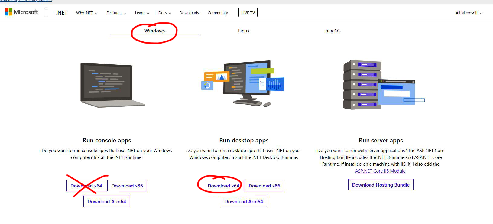
- .NET runtime 6: Another pre-requisite is for the free Microsoft utility ".NET runtime 6" to be installed. Be sure to install the "Download x64" option in the Windows tab under the "Run desktop apps" option as shown below. The download can be found here https://dotnet.microsoft.com/en-us/download/dotnet/6.0/runtime?cid=getdotnetcore
VIP is self updating so installation only needs to be done once. Updates to VIP are pushed to the app when available. The app does not place an icon on the desktop, but you can create a shortcut from the VIP exectable file found at this location on your PC - C:\Program Files (x86)\PPT Group\Vector Instrument Programmer\VectorInstrumentProgrammer.exe.
5.4.2 How to use VIP
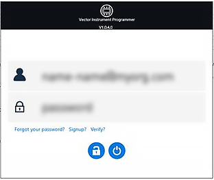
1. Sign in using your Vector Cloud Services account credentials. If you don't have an account, then you can create one by clicking on the "Signup?" option.
2. Connect your Vector device to the PC running VIP using the USB cable tha came with your product. You should see the device appear in the app. I you have more than one device connected then this will be indicated in the top left corner where the USB icon is. You can switch between devices by using the left and right indicators either side of the deice picture.
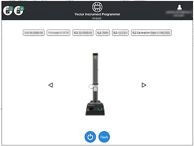
3. To see if there is a firmware update for your device, click on the "Flash" button. A popup will appear asking if you want to update along with the currently installed version and the latest available version. If the version numbers are the same then no action is required and you can select "No" to go back to the home page. If the numbers are different then there is an update available.
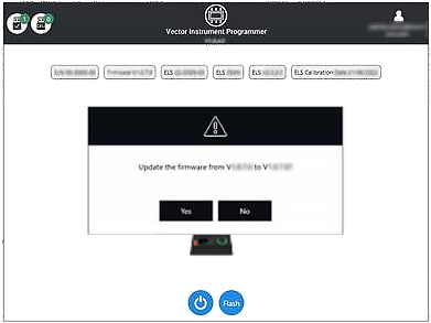
4. If you wish to update, then select "Yes" and the device will automatically update. A progress bar will show the status of the update and once complete the product will power back on and the software will go back to the home screen.
Software updates will be ppublished when updates are released in the software section of our support center at www.Mecmesin.com. If you are unsure or if you need help updating your product please contact support@mecmesin.com.
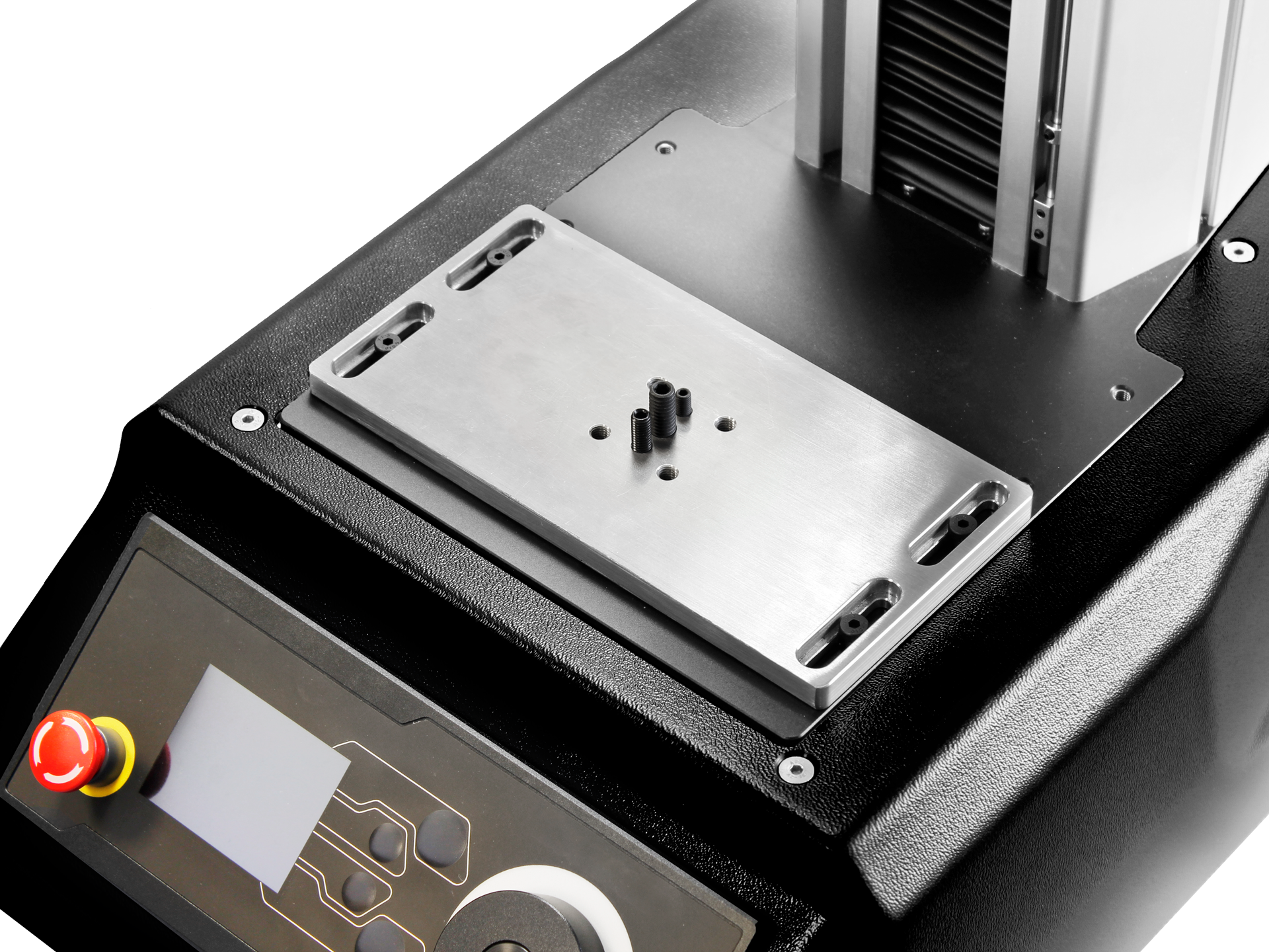
5.5 Attaching Grips and Fixtures
For flexibility of use and alignment of a variety of grips and accessories, the OmniTest single column is fitted with an anvil plate. This plate accept fittings using 4 different screw threads.
The plate is attached with four bolts using a Hex key. For alignment, the anvil plate can be moved forwards or backwards, to adjust the depth of the lower grip or fixture.
Upper grips and accessories are attached directly to the ELS device being used. QC adapters are available and can be fitted directly to the anvil plate or through a Mecmesin MLTE-700 extensometer. For more information relating to the setup of Mecmesin MLTE devices please refer to the MLTE User Manual.
Please Note: A quick connected (QC) fitting type C is required to fit some accessories or grips. This is not supplied as standard with the Omnitest single column. If you do not have a QC fitting, contact your local Mecmesin Distributor for further assistance.
5.6 Setting the Limit Stops
Upper and lower adjustable limit stops are accessible on the front of the OmniTest stand. They prevent crosshead movement beyond a set limit of travel, by inhibiting the machine drive before the crosshead or fixture comes into contact with static parts of the stand.
Their positions should be adjusted after the fitting of fixtures and test samples, to prevent damage to operator, machine or specimens under test.
There are two manually-set limit stops located on the front of the OmniTest single column stand. These are set by loosening the thumb-screw, moving the stop to a new position and retightening, as shown in the image below. When the moving crosshead meets a limit stop, it activates a switch.
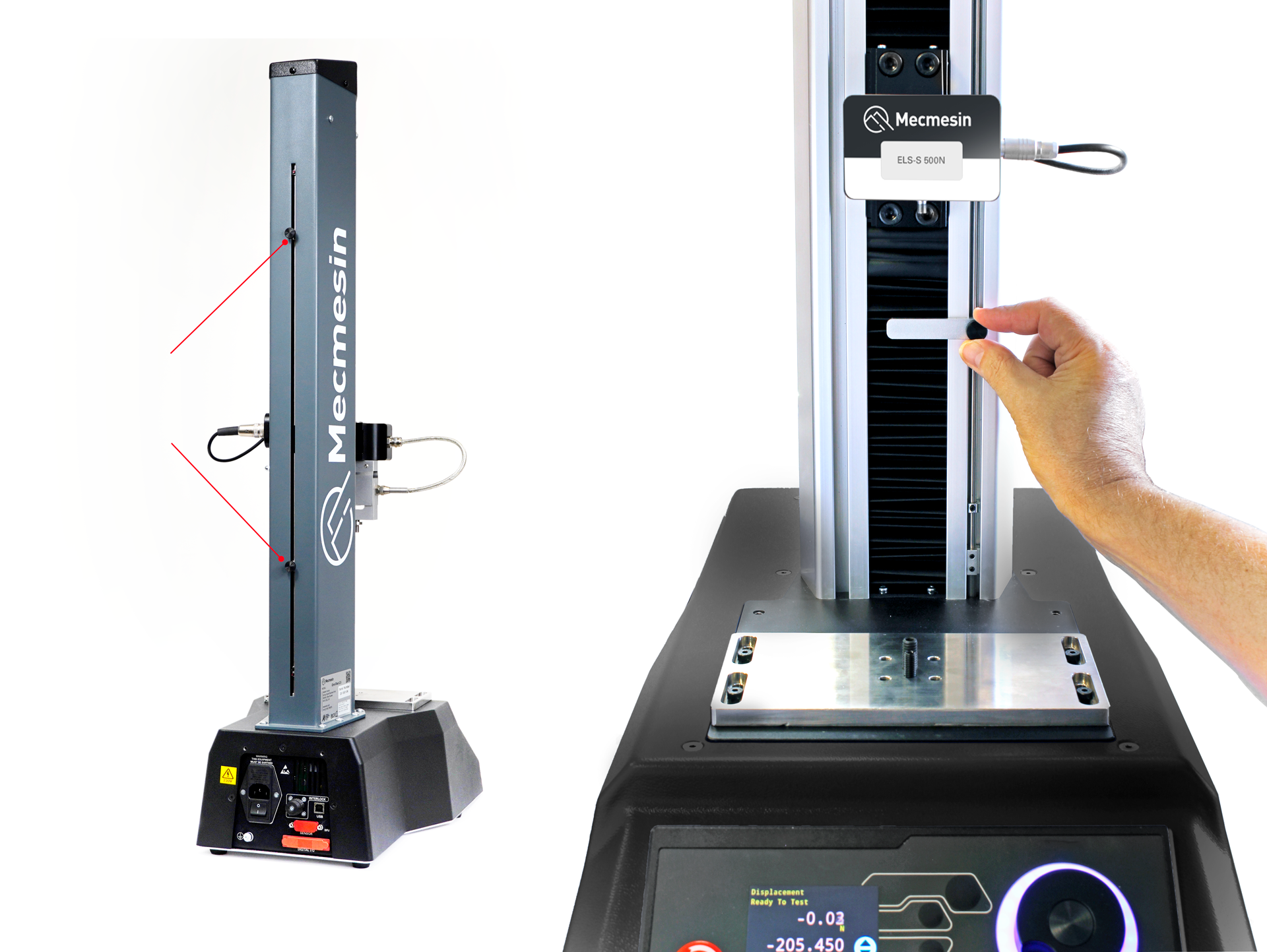
This will stop the crosshead movement at an upper or lower limit during a test sequence. The machine can be driven away from a stop position using the jog controls on the front panel.
6 Enhanced Load Sensor (ELS) Setup
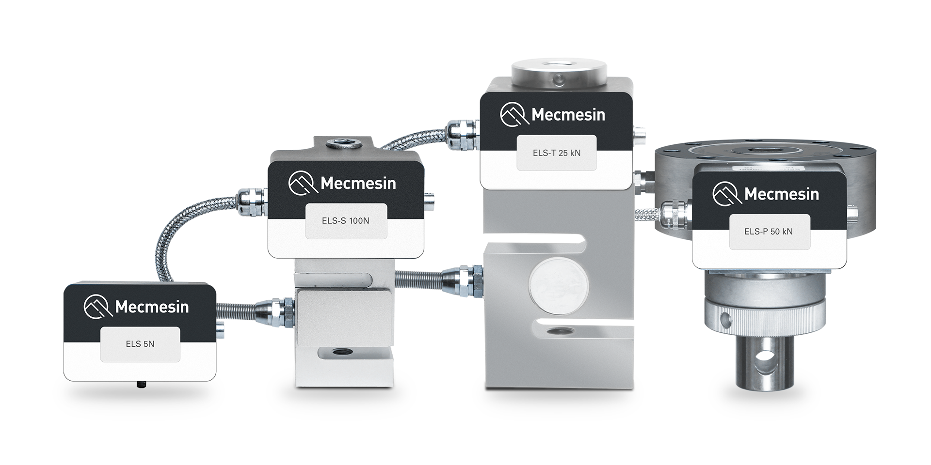
Enhanced load sensors or ‘ELS’ for short, are smart devices used to capture load readings for the OmniTest test stand. All calibration information is held on the individual load cell making them transferable from system to system and the calibration will follow, with no user input required.
These load cells are available in a range of sizes and designs to best suit the individual test requirements. See the specification tables for details relating to capture rate and accuracy.
6.1 Mounting an ELS to an OmniTest 0.5, 1.0, 2.5 and 5 (Dovetail bracket)
These OmniTest models have a dovetail bracket attached to the moving crosshead and will integrate with both ELS (shown right in the image below) and ELS-S type load cells (shown left in the image below).
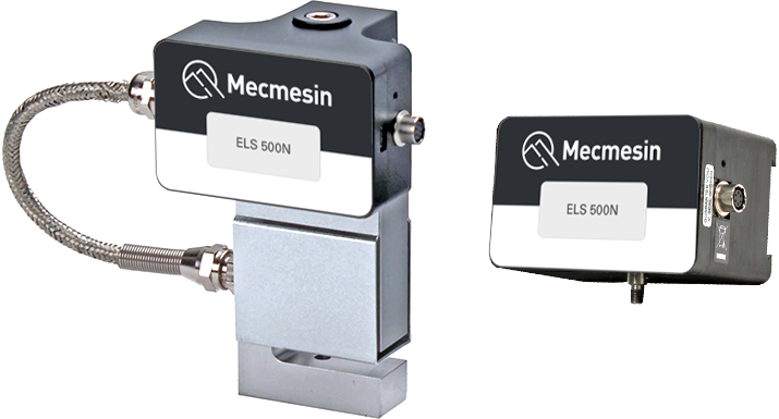
ELS series load cells have a housing that contains an internal load cell, while the ELS ‘S’ series load cells have an ‘S’ beam load cell mounted externally beneath the housing.
To fit the ELS to the test stand, slide the load cell sideways onto the dovetail and tighten the grub screw (circled below in red), located in the dovetail, using a suitable Hex key.

OmniTest 5 Dovetail, note the grub screw circled in red
Please Note: Take care when handling low capacity ELS load sensors such as a 5N cell, as damage can easily occur from mishandling. The load cell should always be lifted by the ELS housing and not the load cell itself.
It is also important to ensure that grips and fixtures attached do not overload the ELS. If in doubt please check the weight of any additional grips and fixtures prior to fitting.
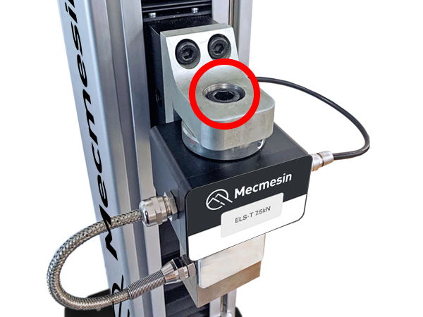
6.2 Mounting an ELS to an OmniTest 7.5
The OmniTest 7.5 uses a right-angled crosshead adaptor to mount an ELS load cell to the moving crosshead. OmniTest 7.5 can only take ELS-T type load cells.
The load cell is tightened to the adaptor using one single centred hex-head screw (highlighted below).
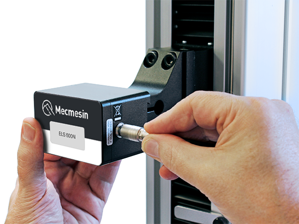
6.3 Connecting an ELS to the OmniTest Stand
To connect the ELS to the OmniTest stand simply plug the 6-pin connector located on the machines crosshead into the ELS fitted, as shown in the image below.
The ELS connector is keyed and should be gently rotated until the connection is securely made. Only a light force is required for this coupling.

Removal of the load cell connection is made by pulling back the outer body and gently removing the two parts.
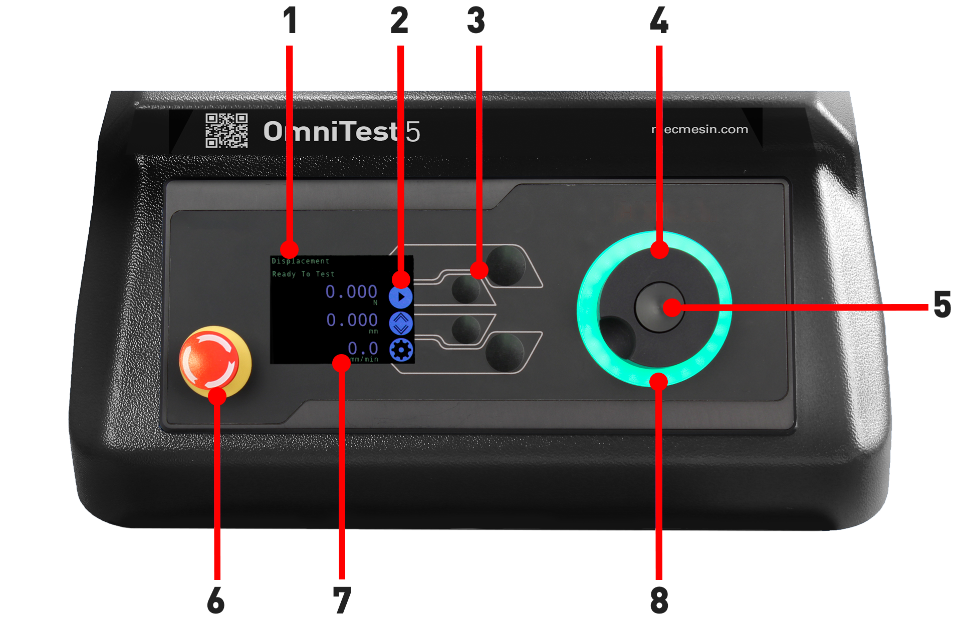
7 Front Panel Controls
|
1 |
Status messages |
|---|---|
|
2 |
Button functions |
|
3 |
Multi-Function selector buttons |
|
4 |
Multi-function scroll wheel |
|
5 |
Scroll wheel button |
|
6 |
Emergency stop |
|
7 |
Display |
| 8 | LED indication dial |
7.1 Emergency Stop
 |
Push the emergency stop button to immediately stop the crosshead movement. Rotate the button to release it and resume crosshead control. If pressed during a test, do not simply restart a test. Ensure any residual force is removed using the test stand’s jog controls before continuing. |
7.2 Multi-function Scroll Wheel Control
7.2.1 Scroll Wheel Colour Indication
The LED light ring surrounding the scroll wheel shows three colours, indicating three states, these states are:
 |
Green Light Pulsating: Ready to start testing Rotating: Scrolling through a menu |
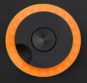 |
Amber Light Static: The current test has completed Rotating: The crosshead is moving |
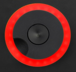 |
Red Light Static: The test has stopped or a limit has been triggered |
7.2.2 Jog Mode
When in jog mode the scroll wheel drives the crosshead directly up (clockwise) or down (anticlockwise). This offers more variable control when compared to the two fixed speed jog control buttons (circled in red below).
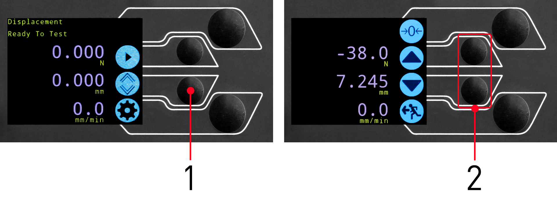
| 1 | Enter jog mode |
|---|---|
| 2 | Jog keys up and down |
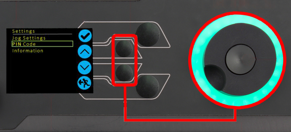
The scroll wheel can also be used as a speed controller. The jog buttons move the crosshead at the set speeds (configured in the ‘Jog Settings’ menu picture below).
Rotating the wheel clockwise whilst holding a jog button will increase the jog speed and rotating the wheel anticlockwise whilst holding a jog button will decrease the speed.
OmniTest single column test stands also feature a precision jog mode, rotating the scroll wheel while holding the central scroll wheel button moves the test stand at its minimum speed, this is useful when fitting specimens into grips or if precision positional control is required.
7.2.3 Navigational Control
The scroll wheel can also be used to navigate the menus. When in a selection menu, the scroll wheel cycles through the selections and their values. This is an alternate navigational option to using the up and down arrow buttons.
7.2.4 The Central Button
The central button is used to confirm a menu selection. It is equivalent to the tick button.
It can also be used to activate fine jog control. Use by rotating the scroll wheel while holding the central scroll button. This drives the test stand at its minimum speed.
7.3 OmniTest Display Panel
The display indicates the stand status, displays live values and is used to configure the test stand settings.
The purposes of the four selection push-buttons are indicated on-screen by an adjacent icon. Below is an image showing a typical example of the on-screen icons in relation to the physical buttons.

| 1 | The top icon is 'Confirm' |
|---|---|
| 2 | The Mid-upper icon is 'Up' |
| 3 | Selection buttons |
| 4 | The Mid-lower icon is 'Down' |
| 5 | The lower icon is 'Back / Exit' |
7.4 Test Stand States
The test stand can be in one of five states:
- Pre-Test - ready to start, or complete,
- Testing – test operation sequence is running,
- Test Stop- test interrupted or emergency stop pressed,
- Jog Mode - for jogging or positioning the crosshead manually,
- Settings Menu – for adjusting the test stand settings,
In each state, the selector buttons have functions described by the on-screen icons.
7.5 On-Screen Icons
On-screen icons vary depending on the current state of the test stand and the menu functions the physical buttons perform at that point. Below are reference tables to help explain the icon definitions.
7.5.1 A: Pre-Test
| Icon | Action |
|---|---|
 |
No sensor connected |
 |
Enable jog mode |
 |
Go to settings |
 |
Move to the home position (Set within VectorPro or test start position) |
7.5.2 B: Test Stop
| Icon | Action |
|---|---|
 |
Stop test: This stops the crosshead movement, leaving the stand in a test- ended status. The message is ‘Interrupted: User’ and the Home or exit/return menu buttons are shown. |
|
Emergency stop button pushed: Message: ‘Emergency Stop!!!!’. Remedy the situation causing the required stop, then release the emergency stop to regain control. Note: there is no on-screen icon for the emergency stop. |
 |
Upper limit switch triggered: The crosshead has reached the upper travel limit, as set by the OmniTest limit switches, and stopped. Further travel in this direction is prevented. |
 |
Lower limit switch triggered: The crosshead has reached the lower travel limit, as set by the OmniTest limit switches, and stopped. Further travel in this direction is prevented. |
7.5.3 C: Jog Mode
| Icon | Action |
|---|---|
 |
Zero (tare) all OmniTest readings |
 |
Move the crosshead upward at the set jog speed |
|
Crosshead has reached an upper limit (load signal from a connected gauge, set to Stop, or a limit switch) and stopped |
 |
Move the crosshead downward at the set jog speed |
|
Crosshead has reached a lower limit (load signal from a connected gauge, set to Stop, or a limit switch) and stopped |
 |
Exit jog mode |
7.5.4 D: Settings Menu
| Icon | Action |
|---|---|
 |
Confirm selection (or press the scroll wheel button) |
 |
Navigate ‘up’ a menu selection or value (or turn the wheel clockwise) |
 |
Navigate ‘down’ a menu selection or value (or turn the wheel anticlockwise) |
 |
Exit settings screen |
8 OmniTest Single Column Settings

All settings are made by moving the selection marker to the required item or digit and confirming with the tick button or using the central scroll wheel button.
8.1 Jog settings
Within the jog settings menu, the parameters for jog speed and force limits while in jog mode can be configured. Below is a detailed breakdown of each setting and the options available for each setting.
|
Setting |
Action |
Range |
|---|---|---|
|
Up Speed |
Configure the jog speed in an upward motion |
0.050 to 1200 mm/min |
|
Down Speed |
Configure the jog speed in a downward motion |
0.050 to 1200 mm/min |
| Jog Timeout Period |
Set the timeout (in minutes) that the machine will keep the motor drive engaged, before the motor drive is disabled. The load applied to the ELS load cell and stand, must reach at least 25 % of the test stand's capacity before the timeout activation is applied. At the end of the timeout period, the 'Jog Active' menu screen is automatically switched back to the 'Ready to Test' menu screen. (Example: OmniTest 5 kN stand fitted with a 2.5 kN ELS, must reach 1250 N in Tension or Compression, before the timeout activation is applied. Forces below the 25 % limit will not activate the timeout and the stand will actively hold the load applied. |
1 to 59 minutes |
|
Return Speed Up |
Configure the Return or Home speed from an initial downward driving direction |
0.010 to 1200 mm/min |
|
Return Speed Down |
Configure the Return or Home speed from an initial upward driving direction |
0.010 to 1200 mm/min |
|
Tension Limit |
Configure the tensile force limit for jog operations |
Up to 2500N (Up to 562 lbf) |
|
Compression Limit |
Configure the compressive force limit for jog operations |
Up to 2500N (Up to 562 lbf) |
8.2 PIN Code
Within the PIN code menu, it is possible to set a four-digit number that can be used to lock the menu feature of the OmniTest system.
8.3 Information
This screen is used to display key information relating to the OmniTest single column stand and connected ELS.
Here the serial numbers, software, hardware and firmware properties, as well as the calibration date for the test stand and the number of overloads that have occurred for the current ELS, are displayed.
9 Automatic ELS Firmware Update
All OmniTest single column test stands with firmware 3.0.1 and above have the ability to update the firmware of any ELS device. This feature is seamlessly managed through the front panel and ensures that the latest firmware is on the ELS devices.
Connect the ELS Device
To start the update connect the ELS to the test system, then switch the test stand on.
Please Note: Analogue short travel extensometers can also be updated in a similar method, simply plug the extensometer device into the corresponding connector on the rear of your OmniTest.
Starting the Upgrade

On the display located on the front panel of the test stand, the screen shown in the image above will be presented.
The new ‘Stored’ firmware is listed at the top of the display and the current ELS firmware is displayed below. In this instance the ELS current firmware is 1.0.8.000, starting the update will flash the device to version 2.1.000.
If more than one ELS is connected (load cell and a short analogue extensometer) the additional devices will be listed. To start the update of the first ELS device press the ‘tick’ icon.
Flashing the Device

The flashing of the device is carried out automatically and progresses through several stages. It is important that the test stand is not turned off or disconnected. Disconnection of the ELS could lead to irreversible damage.
In the image above initial programming is taking place. The progress can be monitored using the bar and percentage readout shown onscreen.
Complete the Flash Process

Once the process is at 100% the display will indicate that the firmware upgrade has been successful. The display panel will then prompt the update of the next ELS device currently connected or the return to the start screen (if no additional ELS devices are connected).
The version of the ELS firmware can be checked manually by accessing the ‘Information’ screen located in the ‘Settings’ menu. See the specification tables for more information.
10 OmniTest Series Specification
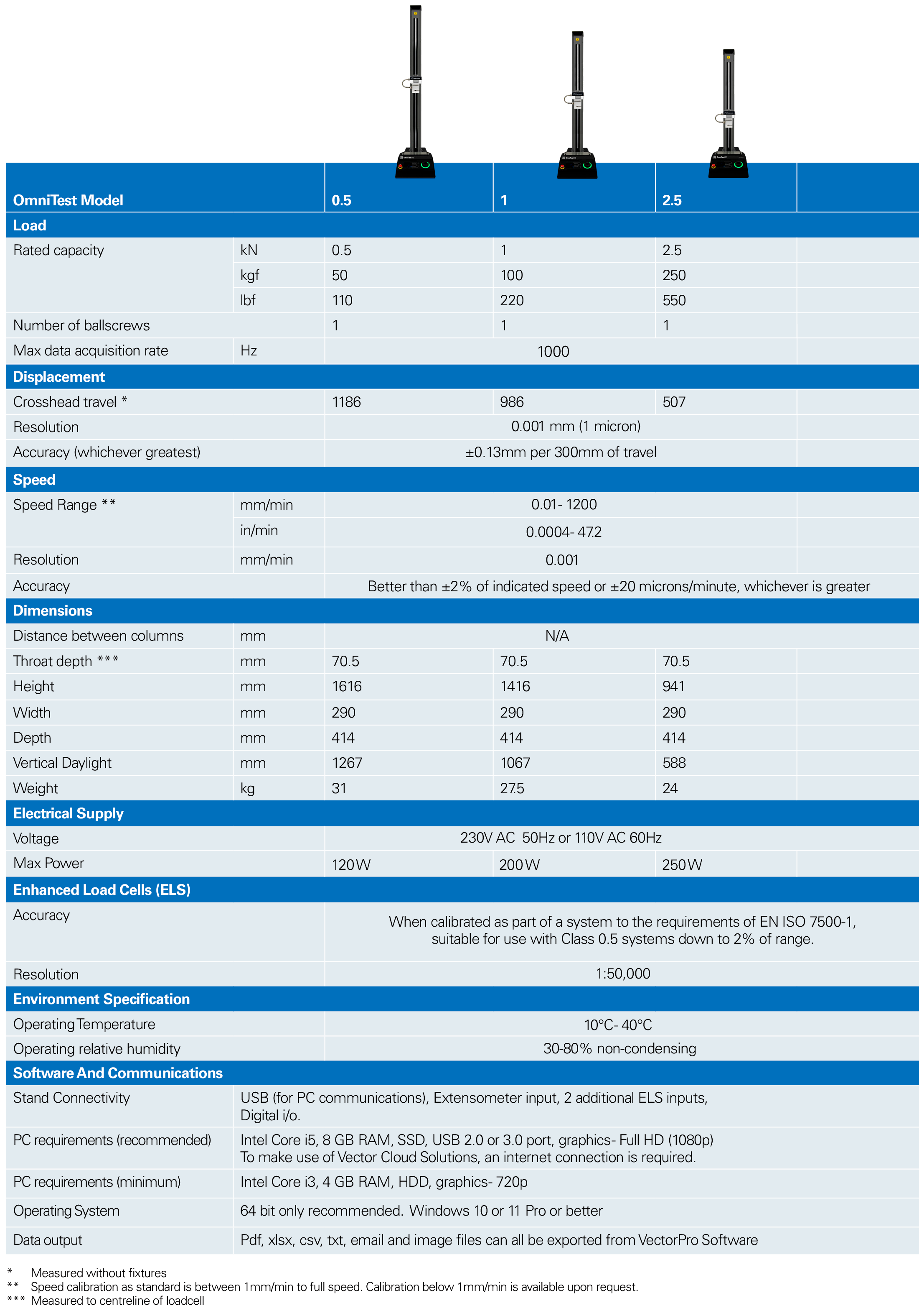
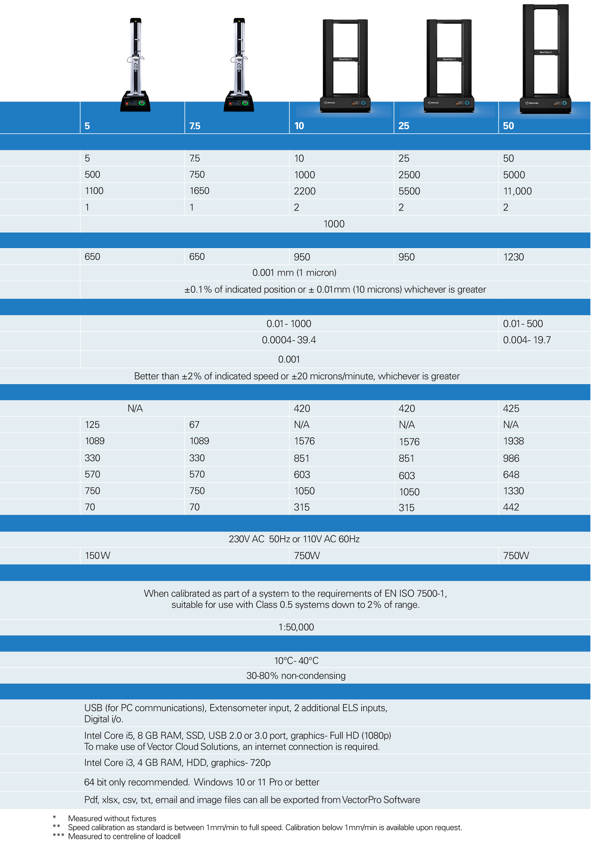
NOTE: Machine wear can be expected over time and may potentially adversely affect both speed and displacement measurement. Machine wear is dependent on factors such as the frequency of usage, harsh operating environments, and the types of test performed (e.g., sudden breaks of stiff materials may cause energy recoil which affects mechanical parts etc.). A full overhaul of the test frame may be required to bring the test system back to its original manufacturer’s specification.
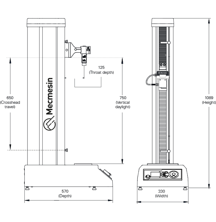
11 OmniTest 0.5 Dimensions
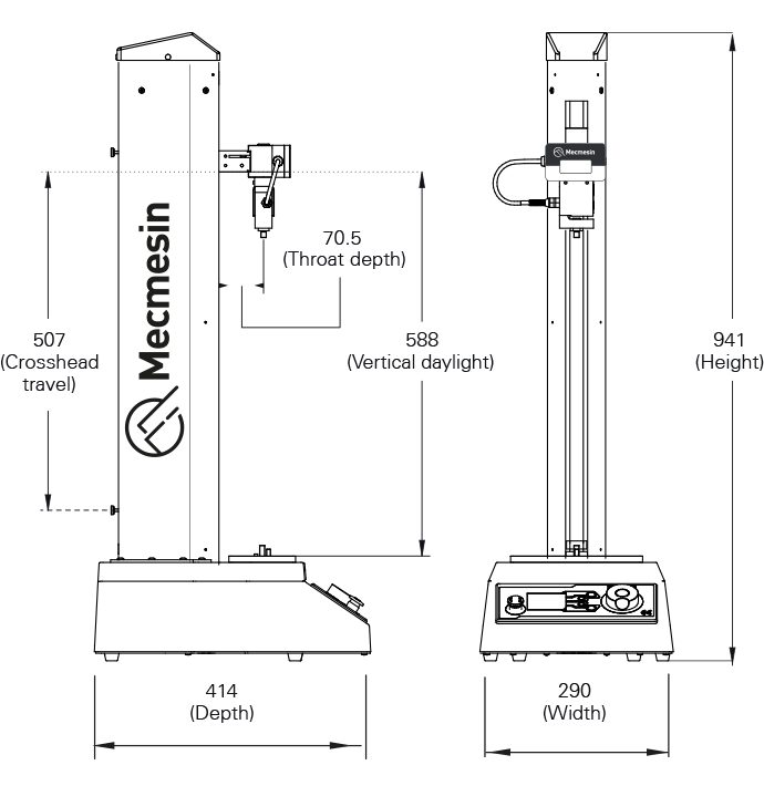
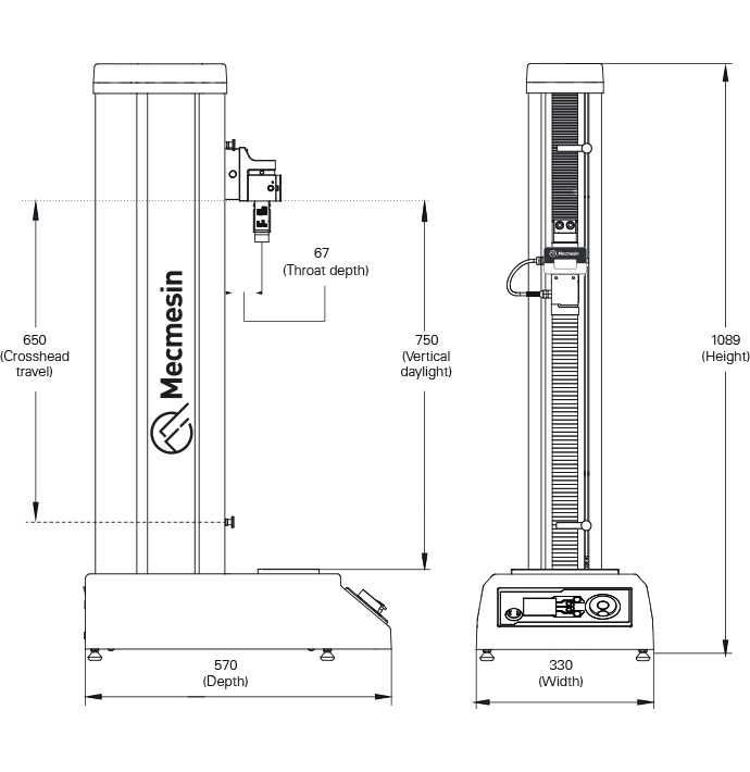
12 OmniTest 1.0 Dimensions
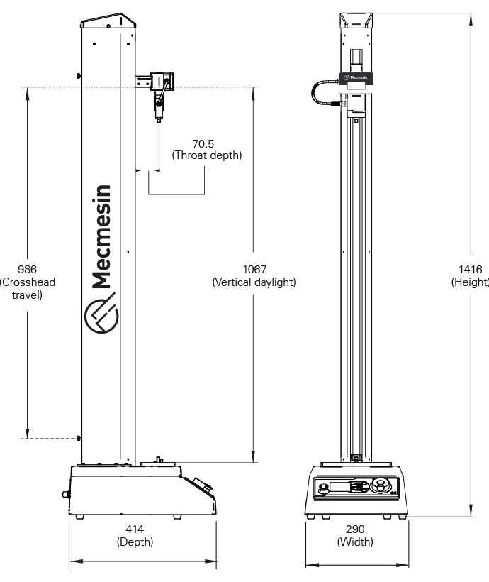
13 Omnitest 2.5 Dimensions
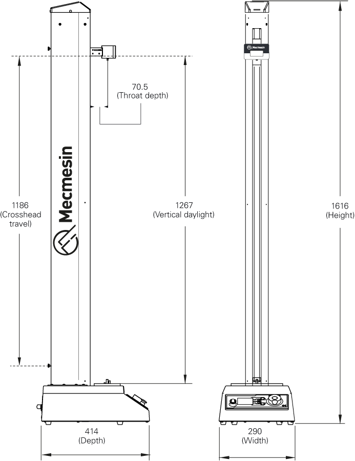
14 OmniTest 5 Dimensions
15 OmniTest 7.5 Dimensions
16 Declaration of Conformity
For the declaration of conformity for the OmniTest range, click here.