
It is essential that you familiarise yourself with the contents of this Assembly and Installation Manual, and the separate Guide to Safe Use of Mains Powered Test Systems before attempting to operate your MultiTest-i or Vortex-i Test System.
- 1 Scope
- 2 Items Supplied with the Test Stand
- 3 Installation
- 4 MultiTest-i Assembly and Installation
- 5 Vortex-i Assembly and Installation
- 6 Connecting the PC (MultiTest-i and Vortex-i)
- 7 Installing Emperor Software on Your PC
- 8 System Specifications
1 Scope
This reference manual covers the following products and their derivatives: (example)
1.1 Force testing stands
Single-column stands:
- MultiTest 0.5-i
- MultiTest 1-i
- MultiTest 2.5-i
- MultiTest 5-i
Twin-column stands:
- MultiTest 10-i
- MultiTest 25-i
- MultiTest 50-i
1.2 Torque testing stand
Vortex–i Torque cell capacities:
- 0.3, 1.5, 3, 6, 10 Nm
2 Items Supplied with the Test Stand
2.1 MultiTest-i test stand
- Test stand
- Four rubber feet, four attachment screws
- Four base anchoring brackets, (if applicable)
- Adjustable handle lever to secure loadcell to crosshead
- At least one Intelligent Loadcell (ILC)
- CD with Emperor™ software
- Mains and data cables
- Manual: Guide to Safe Use of Mecmesin Mains-Powered Test Stands
2.2 Vortex-i test stand
- Test stand
- Intelligent Torque Cell (ITC), as an integral part of the crosshead
- CD with Emperor™ software
- Mains and data cables
- Manual: Guide to Safe Use of Mecmesin Mains-Powered Test Stands
The test stand provides a stable platform with a moving crosshead (force testing) or rotating platen (torque testing). The Intelligent Loadcell measures the force developed, and the Intelligent Torque cell measures the torque applied.
A desktop PC or laptop computer is used to run the Emperor™ software that provides the control of the moving part of the stand, and records, stores and displays the information provided by the measuring cell. Emperor™ is used to create the program for the test, and can make calculations on the received data.
The results of the calculations and the raw data can be printed out or saved in files, and may be exported for remote, secure storage, or may be used for further analysis by other software applications.
The stand communicates with the controlling computer via a USB or serial connection. If other connections are available, then peripheral devices such as printers and network connections can be added.
3 Installation
3.1 Unpacking the stand
When you first receive the stand please check that there is no obvious damage to the packaging. If there is any sign that the packaging or the test stand itself has been damaged, please contact Mecmesin or your authorised distributor immediately. Do not use the stand until you have done so.
We strongly recommend that the packaging is kept, as this can be useful if the machine needs to be returned for calibration.
Section 1 lists items that should be included with your test stand. Please contact Mecmesin or your authorised distributor if any items are missing or damaged.
3.2 Lifting the test stand
The unpackaged weight of the test stand is given in the Specification table at the back of this manual. Do not try to lift heavy loads unaided. Use suitable lifting equipment if necessary.
3.3 Locating the stand
The test stand should be positioned on a suitable, level, stable work surface.
3.4 Mains power supply
Mecmesin –i stands can be used on 110–120 or 220–240 V ac 50-60 Hz supplies. The rear fuse carrier will be set for your local requirement, but is reversible, so should you replace a fuse, the correct local voltage must be selected. The voltage that is selected is the one where the arrows meet (the power inlet is inverted for some test stands):

4 MultiTest-i Assembly and Installation
4.1 Bolting the test stand to the work surface
In order to comply with European regulation and safe use of the equipment, single column stands should be secured to the bench as follows:
| Test stand | Height (mm) | Feet/fixing supplied | Bolting recommended? |
|---|---|---|---|
| 0.5-i | 1616 | Anchor brackets | Yes |
| 1-i | 1416 | Anchor brackets | Yes |
| 2.5-i | 941 | Rubber feet | No |
| 5-i | 1082 | Rubber feet/locating eyes | Yes |
The extended-length test stands MultiTest 0.5-i and MultiTest 1-i are supplied with base anchoring brackets to allow the test stands to be bolted to a bench. Screw the anchoring brackets to the four positions on the base plate of the MultiTest 0.5-i or 1-i using the M6 screws provided. Secure the test stand to the bench using suitable fastenings.

For additional stability the MultiTest 5-i is fitted with two ‘locating eyes’ on the base of the MultiTest 5-i to allow the stand to be bolted to a bench.
Mecmesin twin-column force testing stands and Vortex torque testing stands require no further stability fixing than a flat, secure and stable working surface.

4.2 Fitting the feet to the stand

The MultiTest 2.5-i and MultiTest 5-i are supplied with rubber feet. Support the stand and fit the four rubber feet to the base of the stand.
4.3 Fitting the loadcell to the crosshead
4.3.1 Single-column stands
Ensure the stand is switched off.
Screw the adjustable handle lever with the red button into the crosshead dovetail. This lever is designed to tighten without full rotation. Hold the button on the top to raise and disengage the lever, and turn it away from the direction required. Release and turn, and repeat as required.

On single-column test stands, slide the loadcell (ILC) sideways onto the dovetail bracket at the front of the crosshead. The threaded stud must always be on the underside. Secure the loadcell using the handle lever. Some lateral adjustment is available if needed to align the ILC and a sample. Slacken the lever to make the adjustment, and then re-tighten.
Note: There is some additional adjustment available by moving the anvil plate. Use a 3 mm Allen key to slacken the four retaining screws, reposition the anvil plate and retighten the screws. Align the electrical connector of the ILC with the socket on the test stand. Gently push the connector to locate, then tighten the knurled locking ring in a clockwise direction.

4.3.2 Twin-column stands
The ILC is attached to a twin-column test stand using a cap-head bolt passed through the central hole in the moving crosshead, and secured using the Allen key provided.

4.4 Swapping loadcells
You can swap loadcells by simply disconnecting one cell and fitting another. First, return to the Logon Screen and switch off the stand before unplugging the loadcell. When the new loadcell has been connected, switch the stand on again, and log on again,. After a few seconds the new loadcell will be automatically recognised. Emperor will read in the new cell’s range, serial number and calibration status.
4.5 Attaching grips and fixtures
Grips and other holding fixtures are often paired, with one being attached to the anvil plate, and the other to the underside of the loadcell.
Some fixtures have the QC Quickinterchange system which allows for very rapid changing of the holding accessory.
With the Quick-interchange system, the grip is attached to a mounting using an 8 mm diameter pin. The grip can be fitted and removed without the need for additional tools. Be sure to fit the locking spring to secure the accessory in place.

Take extra care when fitting or removing heavy grips to the underside of the loadcell. Support the accessory while the securing device is removed so that it does not fall.
Before fitting a sample, check that both grips and plates are secure.
4.6 Setting the limit stops
Limit stops are provided to prevent damage to the loadcell and grips. A dual safety system provides protection with the first stage being software controlled, followed, if necessary, by a second hardware limit that removes power from the motor. Upper and lower limit stops can be set to restrict movement of the crosshead.
Limit stops should be adjusted after grips or holding accessories have been fitted so that the limit positions will prevent unwanted contact between moving and static parts.
To set either limit stop, slacken the knurled knob by turning it anti-clockwise, then slide the stop to the desired position and re-tighten the knob again.
Remember to check and, if necessary, adjust the position of the limit stops if the grips are exchanged for different holding accessories.

Twin-column stands have system limit stops as well as limit stops. System limit stops should not be moved.
In an emergency, to release a trapped sample the system limit can be moved, but if you do so, you must contact your Mecmesin distributor for servicing and re-setting. These stops are designed for protection from damage, and moving them may affect your warranty on the stand.

4.6.1 Limits after connection to the PC, with the software running
If the crosshead reaches a limit during a test, it will stop then reverse direction for approximately 5 mm, then stop again. When this happens an onscreen warning message will be displayed:
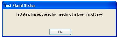
Click OK to acknowledge the warning and use the Jog buttons to move the crosshead so that you can then check the position of the limit stops and re-set if required.
If a limit stop is reached while pressing one of the Jog buttons on the front panel of the MultiTest-i a different warning message is displayed.
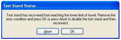
Clicking OK will allow you to correct the situation and continue.
Clicking Abort will disconnect the stand and display the following message:
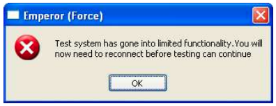
Click OK then Exit to go to the Front Screen, this will reconnect the stand again.
5 Vortex-i Assembly and Installation
5.1 Fitting the crosshead to the Vortex-i
Slide the crosshead onto the two support columns and tighten both securing thumb-screws.
Different height samples can be accommodated by moving the complete crosshead up and down. Additional adjustment is available by moving the top-load carrier.
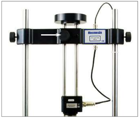
If a top-load is to be used, the securing knob (arrowed) is generally left undone during measurement so the carrier can slide up and down. If a top load is not to be used, securely tighten the locking knob after adjusting to the height required.

5.2 Connecting the intelligent torque cell
Align the electrical connector of the ITC with the mating socket on the test stand. Gently push the connector to locate then tighten the knurled locking ring in a clockwise direction.

5.3 Swapping intelligent torque cells
You can swap the torque cell by simply disconnecting one cell, removing the crosshead and then fitting another. First, log out of Emperor and then switch off the stand before unplugging the torque cell.
When the new torque cell has been connected, switch the stand on again, log on, and after a few seconds the new torque cell will be automatically recognised. Emperor will read in the new cell’s range, serial number and calibration status.
ITC connector
6 Connecting the PC (MultiTest-i and Vortex-i)
6.1 Connecting the power lead and USB lead
Connect the stand to a suitable mains socket. Plug the USB end of the cable into your PC and the D-connector end into the 9-way socket labelled ‘PC’ on the rear of the Vortex or single-column MultiTest stand, or the right hand side of a twin-column MultiTest stand.
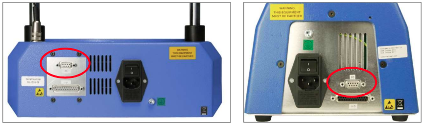
Rear panels of a Vortex-i (left) and MultiTest-i (right). Plug the USB cable into the circled PC socket.
6.2 Emergency stop button
The emergency stop button will stop all movement of the crosshead. Pushing the button will override all other controls. When pressed, the button stays latched down, preventing any movement of the MultiTest crosshead or the Vortex platen. To re-set the button, rotate it about 30 degrees clockwise.
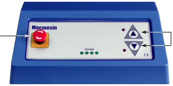
The front panel of the MultiTest 1-i: Emergency stop (left), Jog buttons (right). Vortex-i has a similar emergency stop button and clockwise and anticlockwise jog buttons.
6.3 Jog buttons
Jog buttons are used to position the crosshead or platen so that samples can be attached to the grips. Test Stands have a pair of physical jog buttons on the stand, and another pair of similar buttons on the Emperor screen. The two sets of buttons function in different ways. The physical buttons move the crosshead or platen at a factory-set fixed rate.
Emperor allows you to set either a fixed or variable rate. A variable rate means the jog speed increments (gets faster) or decrements (gets slower) each time an on-screen jog button is clicked.
7 Installing Emperor Software on Your PC
7.1 Minimum system requirements
The minimum specification for the Windows PC is 2 GB RAM and 60 GB free space on the hard drive, running Windows™ XP Pro with SP1, or above. A CD drive is required for installation.
At least one USB port or RS232 port are required for connecting to the system.
7.2 Access to data folders
Emperor will need access to certain folders listed below. Before installing the program, please make sure that read and write access is granted for these folders. In particular if the computer is part of a centrally controlled Windows Domain system, it may be necessary to consult with your IT department to allow correct access to these locations.
| Windows XP User Data location | |
|---|---|
| Emperor Force | C:\Documents and Settings\All Users\Application Data\Mecmesin\Emperor\Force |
| Emperor Torque | C:\Documents and Settings\All Users\Application Data\Mecmesin\Emperor\Torque |
| Windows Vista or Windows 7 User Data location | |
| Emperor Force | C:\ProgramData\Mecmesin\Emperor\Force |
| Emperor Torque | C:\ProgramData\Mecmesin\Emperor\Torque |
| All Windows versions Programe files location | |
| Emperor Force | C:\Program Files\Emperor\Force |
| Emperor Torque | C:\Program Files\Emperor\Torque |
Insert the Emperor CD; Emperor should start automatically and ask if you wish to proceed with the installation of the software.
If the installation program does not start automatically or if you have other problems:
- On your computer desktop click the shortcut to ‘My Computer’
- Click on the CD drive that contains the Emperor software CD
- Navigate to the Emperor folder
- Right click on the Set-up.exe file, and Run as Administrator
Emperor will begin the process of installing the program onto your hard-drive.
Follow the instructions, and accept the license agreement.
You can choose which languages are installed: English only, all languages, or custom, so you can select languages you need.
7.3 Start Emperor
Start the program by using the Emperor icon that was installed on your computer desktop—the splash screen is displayed.
Emperor software provides two levels of user, and a password is used to restrict access to either a simple choice of pre-defined tests or some limited functions, or to give access to the full capabilities of the Emperor system.
Operators can select from tests that are pre-defined, and for which reports have already been written, and some functions that can be assigned to each user account.
Masters have full access to all the functions of the Emperor system. The master user has control over which users are operators and masters.
Logon with a Master level username and password. If this is the first time you have started the program, you can use:
- Default Username: supervisor
- Default Password: supervisor
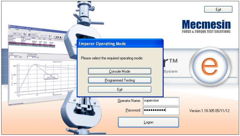
On the Operating Mode selection screen, click on Programmed Testing.
This will start Emperor, and you can set your system preferences, user accounts, create and run test programs, review results, perform calculations for analysis, produce test reports and export data for use elsewhere.
For full details, see the manual: Emperor Programming for Mecmesin Test Systems.
8 System Specifications
8.1 MultiTest-i
| MultiTest-i | 0.5 | 1 | 2.5 | 5 | 10 | 25 | 50 | |
|---|---|---|---|---|---|---|---|---|
| Rated capacity | N kgf lbf |
500 50 110 |
1,000 100 220 |
2,500 250 550 |
5,000 500 1,100 |
10,000 |
25,000 2,500 5,500 |
50,000 5,000 11,000 |
| Number of ballscrews | 1 | 1 | 1 | 1 | 2 | 2 | 2 | |
| LOAD MEASUREMENT | ||||||||
| Available loadcell ranges | N kgf lbf |
2 to 50,000 (14 models) 0.2 to 5,000 (14 models) 0.45 to 11,000 (14 models) |
||||||
| Loadcell accuracy**** | ±0.1% of full scale for loadcells from 2 to 2.5 kN ±0.2% of full scale for loadcells from 5 kN to 50 kN |
|||||||
| Loadcell resolution | 1:6,500 | |||||||
| SPEED | ||||||||
| Speed range | mm/min (in/min) |
1-1000 (0.04-40) |
1-1000 (0.04-40) |
1-1000* (0.04-40) |
1-500 (0.04-20) |
1-1000 (0.04-40) |
1-1000** (0.04-40) |
1-400*** (0.04-15) |
| Crosshead speed accuracy | ±0.2% of indicated speed or ±20 µ/min, whichever is greater***** | |||||||
| DISPLACEMENT | ||||||||
| Crosshead travel†† | 1200 mm (47.3") |
1000 mm (39.4") |
500 mm (19.7") |
590 mm (23.2") |
950 mm (37.4") |
950 mm (37.4") |
1100 mm (43.3") |
|
| Positional accuracy per 300 mm (11.81") of travel | ±130 µm (±0.005") | ±100 µm (±0.004") | ||||||
| Displayed resolution | ±0.01 mm (±0.0004") | |||||||
| DIMENSIONS | ||||||||
| MultiTest-i | 0.5 | 1 | 2.5 | 5 | 10 | 25 | 50 | |
| Distance between columns | — | — | — | — | 400 mm (15.7") |
400 mm (15.7") |
420 mm (16.5") |
|
| Throat depth† | 67 mm (2.6") |
67 mm (2.6") |
67 mm (2.6") |
95 mm |
— | — | — | |
| Vertical daylight†† | 1267 mm (49.9") |
1067 mm (42") |
588 mm (23.1") |
675 mm (26.6") |
1140 mm (44.9’) |
1140 mm (44.9’) |
1330 mm (52.4’) |
|
| Height | 1616 mm (64”) |
1416 mm (56") |
941 mm (37") |
1082 mm (42.6") |
1500 mm (59.1") |
1500 mm (59.1") |
1931 mm (76") |
|
| Width | 290 mm (11.4") |
290 mm (11.4") |
290 mm (11.4") |
328 mm (12.9") |
826 mm (32.5") |
826 mm (32.5") |
864 mm (34") |
|
| Depth | 414 mm (16.3") |
414 mm (16.3") |
414 mm (16.3") |
526 mm (20.7") |
542 mm (21.3") |
542 mm (21.3") |
572 mm (22.5") |
|
| Weight | 31 kg (68 lbs) |
32.5 kg (72 lbs) |
29 kg (64 lbs) |
38 kg (84 lbs) |
140 kg (309 lbs) |
140 kg (309 lbs) |
285 kg (628 lbs) |
|
| Max power requirement | 120 W | 200 W | 250 W | 150 W | 450 W | 450 W | 450 W | |
| Voltage | 230 V AC 50 Hz or 110 V AC 60 Hz | |||||||
* 2.5 kN - recommended maximum speed = 750mm/min (30in/min) above 2 kN
** 25 kN - recommended maximum speed = 500mm/min (20in/min) above 10 kN
*** 50 kN – recommended maximum speed = 250mm/min (10in/min) above 25 kN
**** As the device is used in varying environmental conditions, the uncertainty of measurement could be as much as 0.1% of full scale.
***** Machine wear can be expected over time and may potentially adversely affect both speed and displacement measurement. Machine wear is dependent on factors such as the frequency of usage, harsh operating environments, and the types of test performed (e.g., sudden breaks of stiff materials may cause energy recoil which affects mechanical parts etc.). A full overhaul of the test frame may be required to bring the test system back to its original manufacturer’s specification.
† Measured on centreline of loadcell
†† Measured without loadcell or grips
8.1.1 Common specifications
| Operating temperature | 10ºC - 35ºC (50ºF - 95ºF) |
|---|---|
| Humidity range | Normal industry and laboratory conditions |
| Sampling rate (Hz) | Selectable from 1,000, 500, 100, 50, 10 |
| Compensation for system movement | Yes |
| Loadholding | Yes |
| Digital display of Load/Position/Speed | Yes |
| Output of test results to PC/Printer/Datalogger | Yes, via USB/network ports RS232 via USB/network converter in ASCII format |
| Communication with PLC/Digital Control Interface | Yes, via programmable digital ports 6 inputs + 6 outputs |
8.1.2 Options available on request:
- Column gaiter
- Safety guard
8.2 Vortex-i
| Vortex-i | 0.3 Nm | 1.5 Nm | 3 Nm | 6 Nm | 10 Nm | |
|---|---|---|---|---|---|---|
| Measurement range | Nm kgf.cm lbf.in |
0-0.3 0-3 0-2.7 |
0-1.5 0-15 0-13 |
0-3 0-30 0-26 |
0-6 0-60 0-52 |
0-10 |
| LOAD MEASUREMENT | ||||||
| Load accuracy | ±0.5% of full scale | |||||
| Load resolution | 1:6500 | |||||
| Load units | mN.m, N.cm, N.m, kgf.cm, gf.cm, oz.fin, lbf.ft, lbf.in | |||||
| SPEED | ||||||
| Speed range | 0.1-20 rev/min (clockwise or anticlockwise) | |||||
| Speed accuracy | ±1% of indicated speed | |||||
| Speed resolution | ±0.1 rev/min | |||||
| DISPLACEMENT | ||||||
| Maximum displacement | 2440 revs | |||||
| Displacement accuracy | 0.2° per 36,000° | |||||
| Displayed resolution | 0.001 revs (±0.2°) | |||||
| DIMENSIONS | ||||||
| Max travel of adjustable transducer carriage | 182 mm (7.2") | |||||
| Maximum headroom | 505 mm (19.9") [448 mm (17.6")]* | |||||
| Width between columns | 208 mm (11.02") | |||||
| Weight | 19.5 kg (43 lbs) | |||||
| Capacity of lower mounting table | 10-190 mm (0.39-7.5") | |||||
| Capacity of upper mounting table | 10-78 mm (0.39-3.07") | |||||
| MISCELLANEOUS | ||||||
| Max power requirements | 100 W | |||||
| Voltage | 230 V AC 50 Hz or 110 V AC 60 Hz | |||||
| Loadcell calibration temperature | 20±2°C | |||||
* With upper and lower mounting tables fitted
8.2.1 Common specifications
| Operating temperature | 10ºC - 35ºC (50ºF - 95ºF) |
|---|---|
| Humidity range | Normal industry and laboratory conditions |
| Sampling rate (Hz) | Selectable from 1,000, 500, 100, 50, 10 |
| Compensation for system movement | Yes |
| Loadholding | Yes |
| Digital display of Load/Position/Speed | Yes |
| Output of test results to PC/Printer/Datalogger | Yes, via USB/network ports RS232 via USB/network converter in ASCII format |
| Communication with PLC/Digital Control Interface | Yes, via programmable digital ports 6 inputs + 6 outputs |
8.2.2 Options available on request:
- Safety guard
Mecmesin reserves the right to alter equipment specifications without prior notice.
E&OE
